Expert Engineering Support
AIVON's experienced engineers provide one-on-one DFM and stackup design assistance to ensure your rigid-flex PCB meets both mechanical and electrical performance requirements.
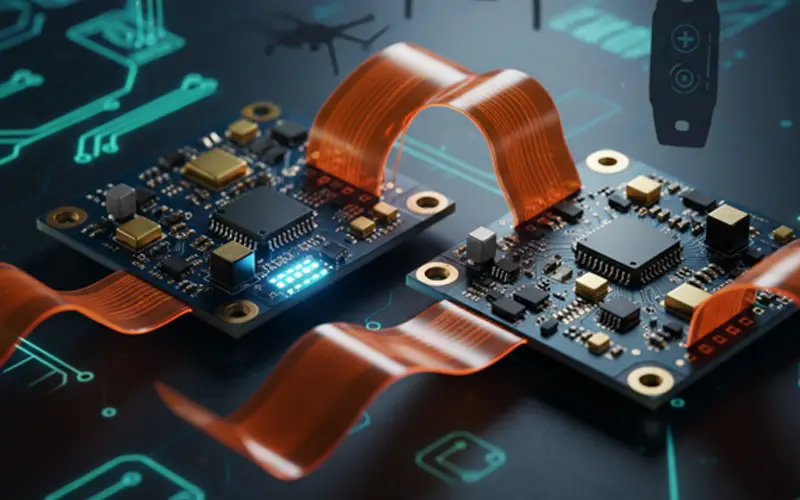
Trusted by global innovators, AIVON provides advanced rigid-flex PCBs for compact, high-performance electronic systems.
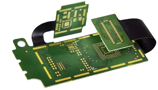
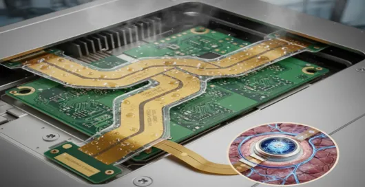
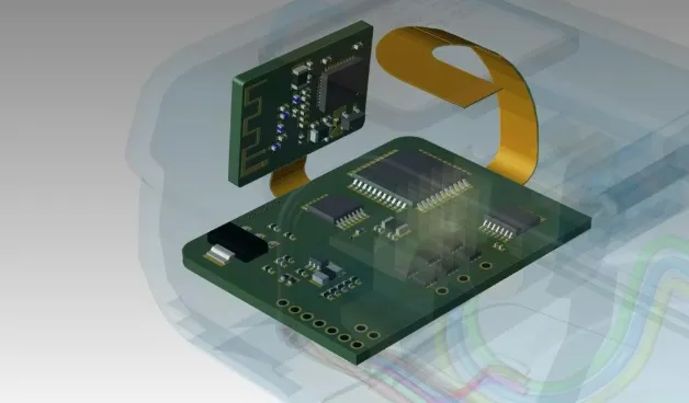
A rigid-flex PCB combines rigid and flexible circuit layers into a single structure, offering both durability and design flexibility. It allows 3D configurations, reduces connectors, and improves reliability. AIVON's rigid-flex PCBs are ideal for compact, high-performance devices requiring stable signal integrity and mechanical strength.
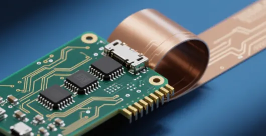
The flexible section of a flex or rigid-flex PCB can be bent, folded, or routed in three dimensions, allowing designers to bypass internal mechanical obstructions and densely packed components. This capability significantly improves internal layout efficiency and reduces the overall product size. For example, in consumer electronics such as smartphones and tablets, using flexible circuits in hinge areas, battery connections, and display modules can reduce device thickness by up to 30%, enabling sleeker and more compact designs. In wearables, flexible PCBs allow electronics to conform to curved surfaces, maximizing space without sacrificing performance.
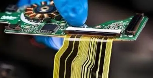
Flexible PCBs enhance system reliability by minimizing the number of solder joints, connectors, and wiring harnesses—common failure points in traditional assemblies. Fewer interconnects can reduce the failure rate by up to 50% during long-term operation. Additionally, the integrated structure of flexible circuits provides strong resistance to vibration, impact, and thermal cycling. These advantages make them highly suitable for automotive-grade applications such as in-vehicle sensors, ADAS cameras, dashboard modules, and engine-bay electronic control units, where durability and stability are critical under harsh operating conditions.
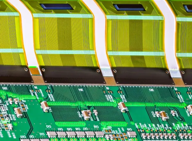
Fine-pitch traces in the flexible area, often with line width/spacing ≤ 0.1 mm, help minimize signal attenuation and electromagnetic interference. Combined with advanced stack-up design and high-performance materials, flexible PCBs can achieve ±7% impedance control accuracy, ensuring stable signal transmission even at very high frequencies. These characteristics make them ideal for 5G communication infrastructure, high-speed data transmission modules, RF antennas, camera signal lines, and other applications requiring low loss and high-frequency reliability.
Flexible PCBs typically use polyimide (PI) substrates, offering exceptional thermal and chemical resistance. PI materials withstand temperatures above 260°C, maintain excellent dimensional stability, and resist corrosion from oils, solvents, and industrial chemicals. When combined with protective surface treatments, such as conformal coatings for dustproof, moisture-proof, and oxidation resistance, flex circuits can reliably operate in harsh environments. They are widely applied in industrial automation equipment (e.g., robots, SMT equipment, high-temperature workshops), aerospace systems, medical implantables, and other devices requiring long-term performance in challenging conditions.
AIVON's experienced engineers provide one-on-one DFM and stackup design assistance to ensure your rigid-flex PCB meets both mechanical and electrical performance requirements.
Equipped with precision laser drilling, automated lamination, and high-speed routing machines to guarantee tight tolerances and superior interlayer bonding.
Supports a wide range of materials, including Polyimide, FR4, and hybrid Rogers composites, for optimized flexibility and signal integrity.
Each PCB undergoes multi-stage inspection: AOI, X-ray, E-test, and bend testing to ensure flawless reliability and long-term durability.
Whether you need small prototypes or full-scale mass production, AIVON's flexible manufacturing lines can adapt to your project needs efficiently.
With fast lead times and international logistics support, AIVON ensures your rigid-flex PCB projects are delivered on time, every time.

Applied in fast chargers, laptop power adapters, LCD TV backlight driver boards, projector light source control boards, and more.

Used in driver boards for automotive LED headlights (both low beam and high beam), as well as control boards for interior ambient lighting.

Applied in low-voltage control circuits of inverters, signal amplification boards for sensors, auxiliary circuits of small and medium-sized switching power supplies, and uninterruptible power supply (UPS) systems.

Used in LED ceiling lights, downlights, spotlights, LED street lights, tunnel lights, and garden lights.
.webp)
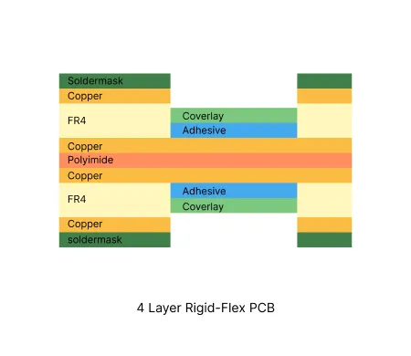
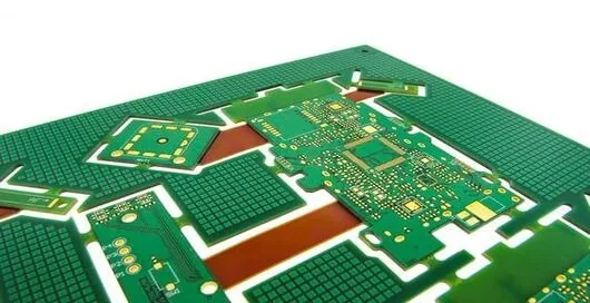
4 layer rigid-flex constructions deliver high density circuitry with mechanical flexibility for aerospace, medical, and industrial applications.
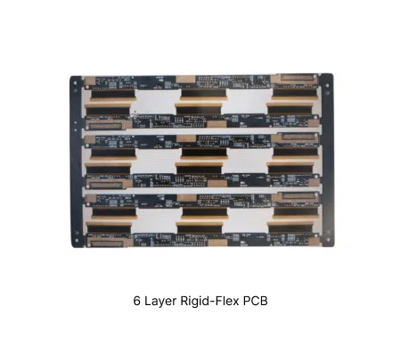
Advanced 6-layer rigid-flex constructions combine mechanical stability with dynamic flexing capability for demanding electronic applications.
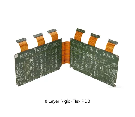
These boards combine multiple rigid zones with flexible interconnects. The construction supports complex routing in space-constrained dynamic applications.
Master the complexities of Rigid-Flex PCB Design with this 2,500-word guide. Explore stack-up symmetry, bend radius calculations, via optimization, and cost-effective manufacturing strategies.
Optimize your Rigid-Flex PCB Assembly with our expert guide. Explore advanced substrates, high-speed impedance control, and DFM best practices to ensure a smooth production process and maximum reliability for complex systems.
Explore the top rigid-flex PCB applications in aerospace, medical, and consumer electronics. Learn how these boards enhance reliability and optimize space in modern designs.
A1: The higher cost is due to the increased complexity of the manufacturing process, which involves unique steps like differential etching, complex multi-layer lamination of dissimilar materials, and rigorous testing protocols for both rigid and flexible sections. The specialized flexible materials themselves are also more expensive than standard rigid materials.
A2: Lead time depends on complexity and volume—typically 7–15 working days for prototypes and 2–4 weeks for mass production orders.
A3:They offer excellent space efficiency, mechanical stability, and design flexibility, reducing the need for connectors and improving signal integrity.


