










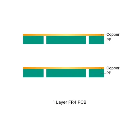
1 Layer FR4 PCB
Discover how AIVON manufactures 1 Layer FR4 PCBs, including single-sided board structures, material selection, cost-efficient fabrication processes, manufacturing challenges, and real production experience from customer orders.
Standard and high-Tg FR4 PCBs for prototypes, small batches and production, with flexible layer counts, copper weights and surface finishes.


FR4 is a glass-reinforced epoxy laminate widely used as the base material for printed circuit boards. It is made by impregnating woven glass fiber with epoxy resin and pressing the layers together under controlled heat and pressure. Known for its excellent mechanical strength, and moisture resistance, FR-4 material provides a stable base for copper layers and ensures consistent signal performance.
Standard FR4 is commonly used for general-purpose PCB fabrication, while higher-Tg grades are often selected for applications that require greater thermal stability, particularly in multilayer boards and lead-free assembly processes.


Choosing the right FR4 material can affect a PCB's thermal performance, electrical properties, mechanical stability, and long-term reliability. This Guide explains the material structures and properties behind FR4 PCBs, helping engineers understand how different material options relate to PCB design and manufacturing requirements. The guide covers the main components of FR4 laminates, including copper-clad laminate, prepreg, glass styles, and resin systems. It also explains important material classifications such as standard-Tg, mid-Tg, and high-Tg FR4.

Designing a PCB with FR4 involves more than placing components and routing traces. The material's electrical and mechanical properties influence layer configuration, trace dimensions, impedance, thermal considerations, and overall manufacturability. The guide begins with the fundamentals of FR4 material and explains how its properties relate to PCB design. It then walks through the main design workflow, including defining circuit requirements, creating schematics, arranging components, routing traces, setting design rules, running Design Rule Checks, and exporting Gerber files for manufacturing.
Discover how AIVON manufactures 1 Layer FR4 PCBs, including single-sided board structures, material selection, cost-efficient fabrication processes, manufacturing challenges, and real production experience from customer orders.
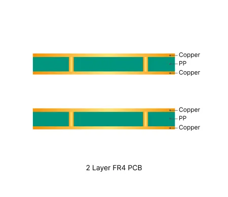
Discover how AIVON manufactures 2 Layer FR4 PCBs, including double-sided circuit structures, reliable through-hole fabrication processes, manufacturing challenges, and real production experience from customer orders.
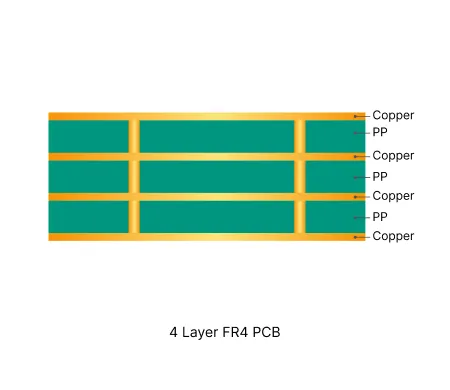
Discover how AIVON manufactures 4 Layer FR4 PCBs, including multilayer stackup design, layer alignment control, fabrication processes, manufacturing challenges, and real production experience from customer orders.
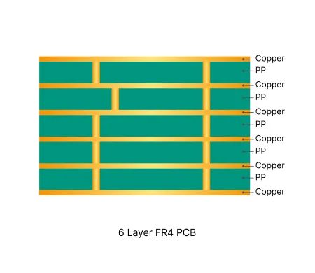
Discover how AIVON manufactures 6 Layer FR4 PCBs, including multilayer stackup optimization, impedance control requirements, fabrication processes, manufacturing challenges, and real production experience from customer orders.
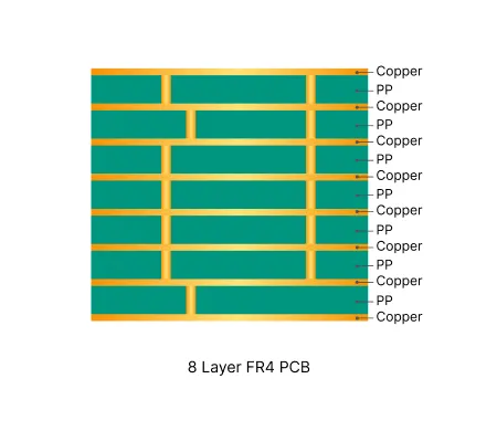
Discover how AIVON manufactures 8 Layer FR4 PCBs, including advanced multilayer structures, signal integrity requirements, impedance control, fabrication processes, manufacturing challenges, and real production experience from customer orders.
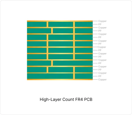
These high-layer count FR4 PCB enable high-density interconnects while maintaining signal integrity and thermal reliability in computing and communication equipment.
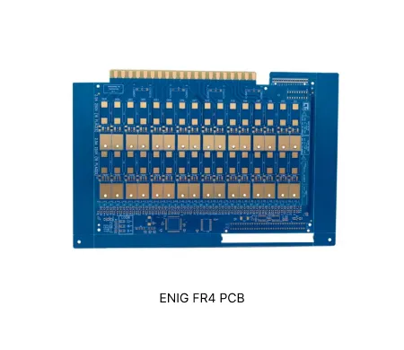
Discover how AIVON manufactures ENIG FR4 PCBs, including electroless nickel immersion gold surface finishing, solderability requirements, fabrication processes, manufacturing challenges, and real production experience from customer orders.
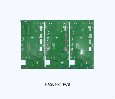
Discover how AIVON manufactures HASL FR4 PCBs, including hot air solder leveling processes, surface finish control, fabrication processes, manufacturing challenges, and real production experience from customer orders.
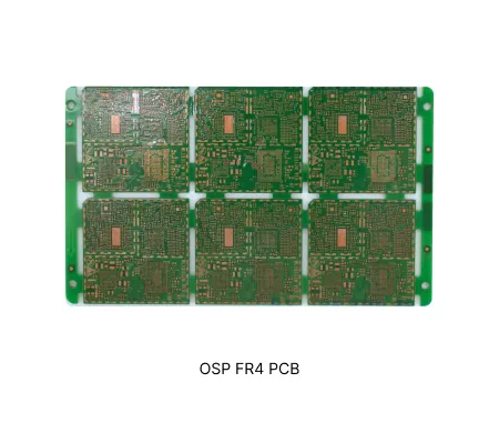
Discover how AIVON manufactures OSP FR4 PCBs, including organic surface protection requirements, copper surface preservation, fabrication processes, manufacturing challenges, and real production experience from customer orders.
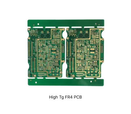
Discover how AIVON manufactures High Tg FR4 PCBs, including high-temperature material selection, thermal reliability requirements, fabrication processes, manufacturing challenges, and real production experience from customer orders.
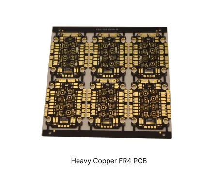
Discover how AIVON manufactures Heavy Copper FR4 PCBs, including high copper weight requirements, current carrying capability, thermal performance optimization, fabrication processes, manufacturing challenges, and real production experience from customer orders.
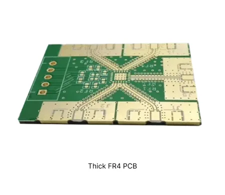
Discover how AIVON manufactures Thick FR4 PCBs, including increased board thickness control, mechanical reliability requirements, fabrication processes, manufacturing challenges, and real production experience from customer orders.
| Order ID | PCB Type | Layers | Dimensions | Solder Mask | Surface Finish | Quantity | Action |
|---|---|---|---|---|---|---|---|
| Loading... | |||||||
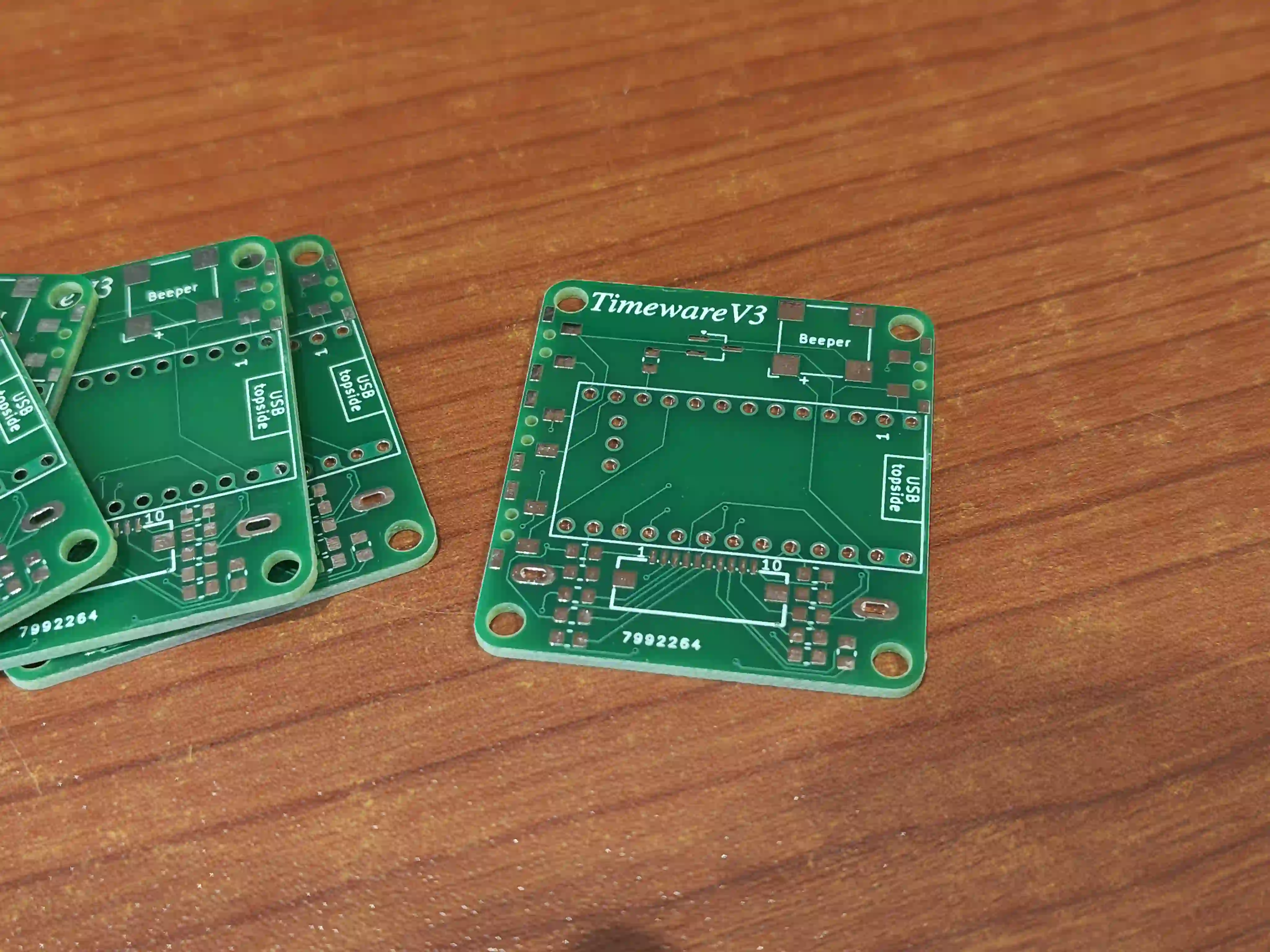
 AI*****S2

FR-4, 2-Layer, 38.8mm * 42.8mm, Green, HASL Lead Free, 5 PCS
The PCB is great! silkscreen printing is clear and the edges are smooth.
See how this PCB was manufactured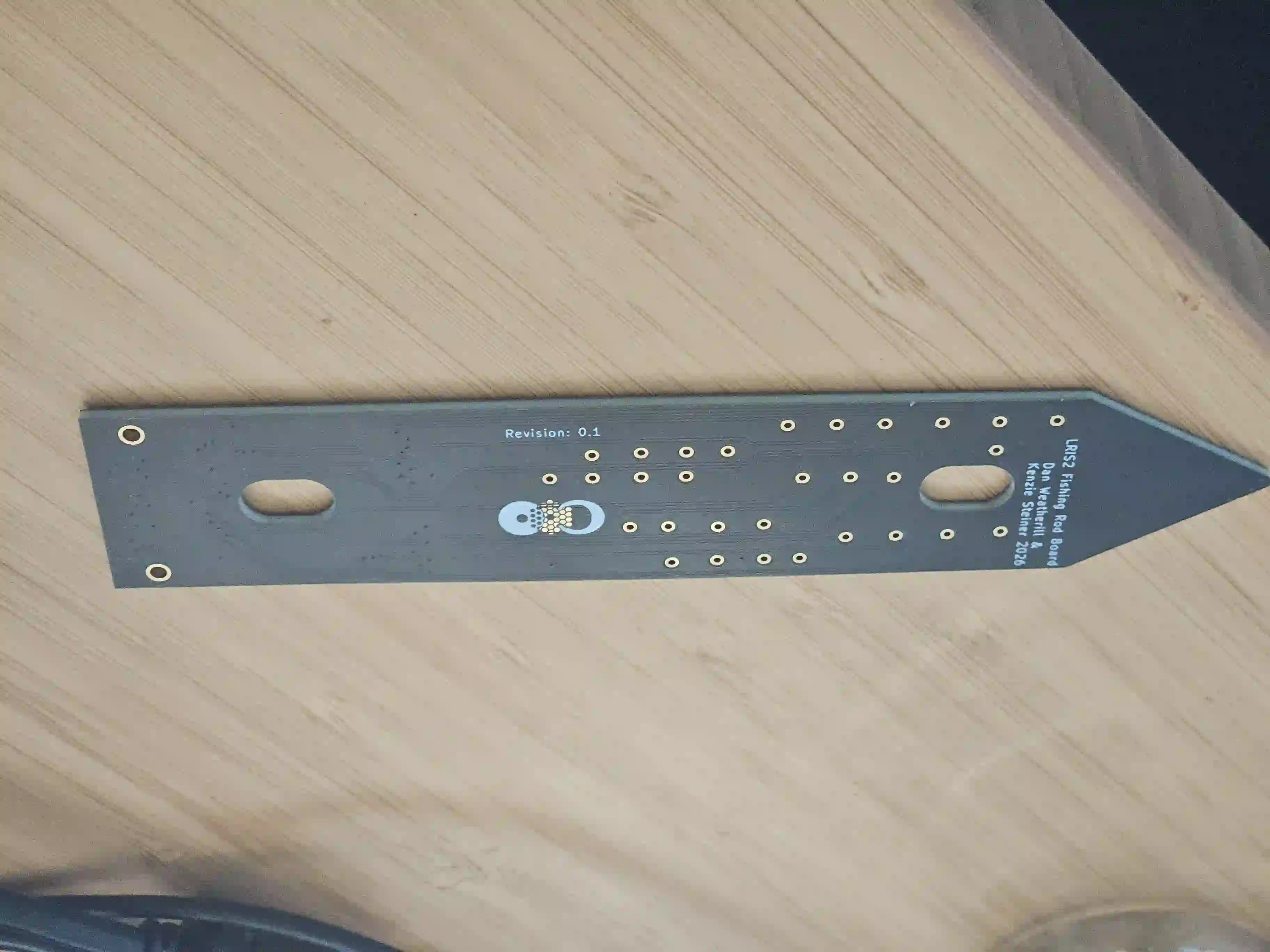 AI*****S5

FR-4, 4-Layer, 25mm * 124mm, Matte Black, ENIG (Immersion Gold), 10 PCS
Excellent quality as always from Aivon and fast processing time
See how this PCB was manufactured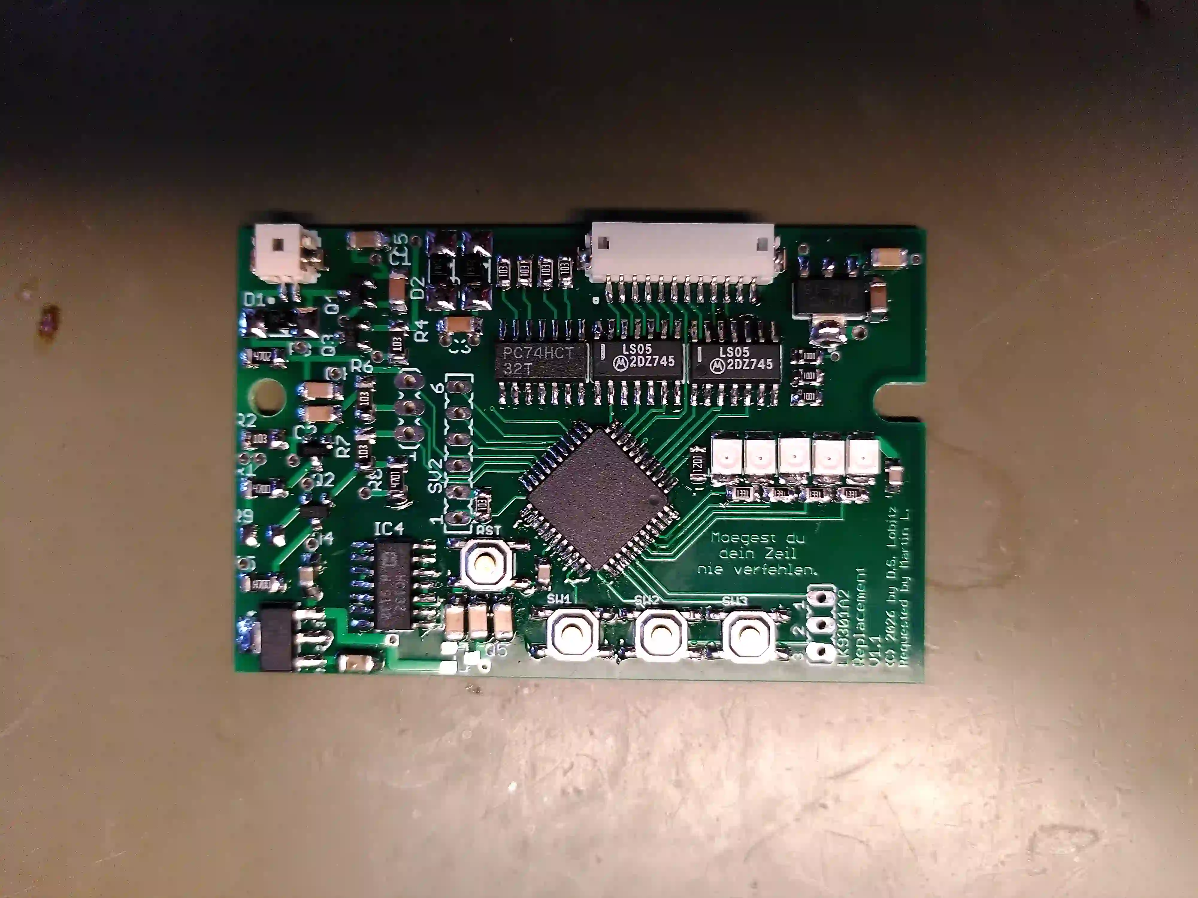 AI****9A

FR-4, 4-Layer, 67mm * 43.7mm, Green, HASL Lead Free, 10 PCS
The quality of the PCBs is outstanding, especially considering the highly competitive pricing. Communication with my account manager is always excellent, helpful, and highly efficient. Furthermore, despite shipping from overseas, the delivery arrived within just three working days. Finally, the web interface strikes a perfect balance: it is very intuitive and well-structured for quick tasks, yet it provides experienced users with all the advanced features and technical capabilities an engineer could ask for.
See how this PCB was manufactured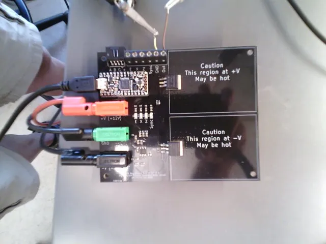 AI*****S2
FR-4, 2-Layer, 120mm * 100mm, Black, HASL Lead Free, 5 PCS
I got the boards a couple days ago and have already built and tested the first circuitboard. The boards are of excellent quality, they work flawlessly, and this physics instrumentation project is completed in part thanks to the great service and fair prices of AIVON.com. I am a very happy customer and will be using their services again!
See how this PCB was manufactured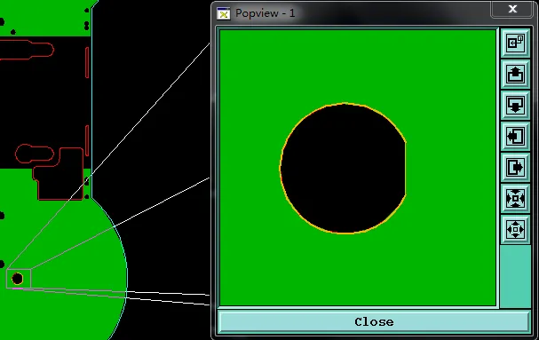 PCB Copper Weight
Learn how our CAM team resolved countersink dimension mismatches, copper thickness conflicts, and D-hole clearance problems on a 3mm thick FR4 PCB. This real engineering case shows critical DFM checks for precision countersink holes in FR4 PCB to prevent assembly failures and ensure reliable production.
 4-Layer PCB
Learn how CAM engineers fix countersink depth conflicts, edge proximity risks, and hole-file offsets on thin 0.8 mm 4-layer FR4 boards to prevent breakout and yield loss.
 PCB Materials
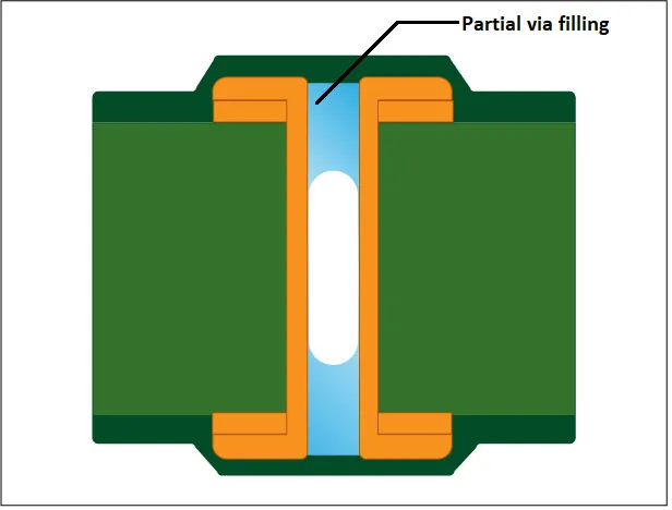
Struggling with EQs? Discover why High Tg FR4 PCB designs often hit bottlenecks. Learn to optimize your high-tg fr4 laminate selection, resin fill for heavy copper, and via plugging to ensure thermal reliability and bypass the common pitfalls of TG 180 manufacturing.

FR4 circuit boards are commonly used in computers, home appliances, gaming devices, and other consumer products where cost effective multilayer designs provide the required electrical and mechanical performance.

FR4 boards are used in diagnostic equipment, monitoring systems, laboratory instruments, and medical control electronics where dimensional stability and consistent electrical performance are important.

FR4 PCBs are used in engine control units, body control modules, infotainment systems, and other automotive electronics that require reliable multilayer circuits and resistance to thermal and mechanical stress.

FR4 printed circuit boards are used in routers, switches, base stations, and communication equipment where multilayer structures support dense routing, power distribution, and high speed signal transmission.

FR4 PCBs are widely used in PLCs, motor controllers, power control systems, and industrial automation equipment where stable mechanical structure and reliable long term operation are required.

Used in avionics, navigation systems, communication equipment, and control electronics where stable multilayer construction and reliable electrical connections are required under demanding operating conditions.

The Tg, or glass transition temperature, is an important factor when selecting an FR-4 material for PCB fabrication. It indicates the temperature at which the resin system begins to transition from a rigid glassy state toward a softer state, affecting thermal expansion, dimensional stability, and reliability during PCB processing and operation.
Common FR-4 material grades include TG130, TG150, and TG170. TG130 is generally used for standard PCB applications where thermal demands are moderate.
TG150 provides a higher thermal margin and is widely considered for multilayer boards and applications that undergo lead-free assembly. TG170 is a higher-Tg option for designs with greater thermal stress, repeated thermal exposure, or more demanding reliability requirements. The actual performance of each material depends on the specific laminate system and manufacturer's datasheet, rather than the Tg value alone.
AIVON supports different FR-4 material options for prototype and production builds, with material selection coordinated with board construction, layer count, copper weight, thickness, and required manufacturing specifications.
A1: Standard FR4 materials typically have a Tg around 130°C, while higher-Tg options commonly include TG150 and TG170 grades. The appropriate Tg depends on the PCB's operating temperature, assembly process, layer structure, and reliability requirements. For lead-free assembly or designs exposed to greater thermal stress, a higher-Tg FR4 material may provide a greater thermal margin.
A2: 1.6 mm is the most common finished thickness for a standard FR4 PCB, but manufacturers can produce boards in thinner and thicker configurations. Common options in AIVON's manufacturing include 0.8 mm, 1.0 mm, 1.2 mm, 1.6 mm, and 2.0 mm. The suitable thickness depends on mechanical requirements, layer count, impedance requirements, connectors, enclosure constraints, and the final stack-up.
A3: FR4 PCBs can be manufactured as single-layer, double-layer, or multilayer boards. The practical layer count depends on the board's stack-up, thickness, registration requirements, via structure, and the manufacturer's equipment and process capability. Standard multilayer FR4 production commonly covers designs from a few layers to high-layer-count boards, with more complex constructions requiring tighter lamination and registration control.
A4: A single-sided FR4 PCB has conductive copper on one side of the substrate, while a double-sided FR4 PCB has copper layers on both sides and can use plated through-holes to connect the two layers. Single-sided boards are suitable for simpler, lower-density circuits, while double-sided FR4 PCBs provide more routing space and are better suited to designs with higher component or circuit density.
A5: Standard FR4 can be used for many digital and moderate-frequency applications, but it is not a universal choice for high-frequency designs. Its dielectric constant and dissipation factor vary by material system, glass style, resin content, frequency, and test method. As frequency increases, dielectric loss and dielectric-property variation can become more significant, so engineers may need to evaluate the specific FR4 datasheet or consider a lower-loss laminate for demanding RF and high-speed applications.


