










Superior Signal Transmission

Low loss and strong anti-interference ensure excellent high-frequency signal integrity.
High Frequency PCBs Engineered for Performance, Stability, and Reliability


High Frequency PCBs are mainly used in RF, communication, and radar systems operating above 1 GHz. They are fabricated with high-frequency materials such as PTFE, Rogers, and Taconic, known for their stable dielectric properties. Through precise impedance control, optimized layer stacking, and fine etching processes, these boards effectively reduce signal attenuation and phase distortion, ensuring high accuracy and consistency in high-frequency signal transmission.
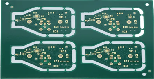
Designed for compact and lightweight devices
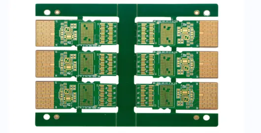
Multilayer circuit board designed for ultra-high-frequency, ultra-high-speed, and multi-channel applications
Low loss and strong anti-interference ensure excellent high-frequency signal integrity.
Supports GHz-level frequency and high-speed data transmission for 5G, AI, and advanced communication systems.
Precisely engineered trace widths, spacing, and dielectric properties ensure consistent impedance, minimizing signal reflection and maintaining high signal integrity across complex high-frequency circuits.
High-precision fabrication and premium materials provide excellent heat resistance, corrosion protection, and durability in complex environments.
Ultra-fine traces and multilayer structures enable device miniaturization and high-performance system integration.
Advanced substrate materials and copper layering quickly dissipate heat from high-frequency components, reducing thermal stress and improving long-term reliability in demanding RF and communication applications.

Used in communication modules and cockpit domain controllers for in-vehicle Ethernet systems (1000BASE-T1 / 10GBASE-T1).

https://cdn.aivon.com/aivon/product/20251202/Consumer Electronics.webp

Used in high-speed sampling boards for Battery Management Systems (BMS).

Applied in RF units of 5G/6G base stations, and high-speed backplanes and line cards of data center routers and switches.

Used in radar systems, satellite communication modules, avionics control units, and other high-reliability electronic systems that require extreme thermal stability, vibration resistance, and signal integrity.
End-to-End Quality Control:
Raw materials are sourced from top brands such as Rogers, Panasonic, and Shengyi. Each batch comes with certified reports for Dk/Df, CTE, and Tg values. XRF testing ensures halogen- and heavy-metal-free compliance with RoHS standards. Rigorous Testing System: Equipped with advanced inspection equipment, every PCB undergoes comprehensive factory testing to ensure it meets strict quality standards.
Traceability System:
Each PCB is laser-etched with a unique UID code. Scanning it provides full traceability, including material batch, impedance test curve, AOI inspection results, and reliability test data.
Discover how solder mask dielectric constant and loss tangent impact high-frequency PCB performance. Learn to choose low-loss solder mask materials for superior signal integrity.
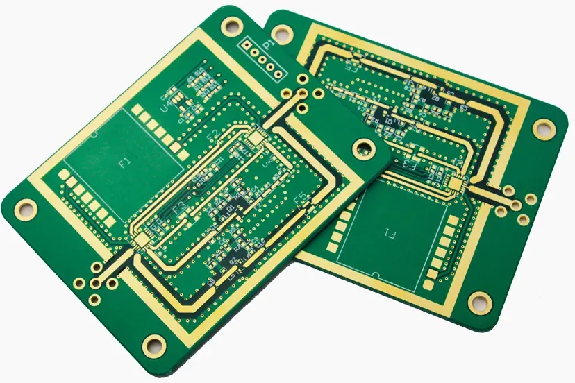
Explore how Electroless Nickel Immersion Gold (ENIG) surface finish affects signal loss, insertion loss, and impedance control in high-frequency and RF PCB applications.
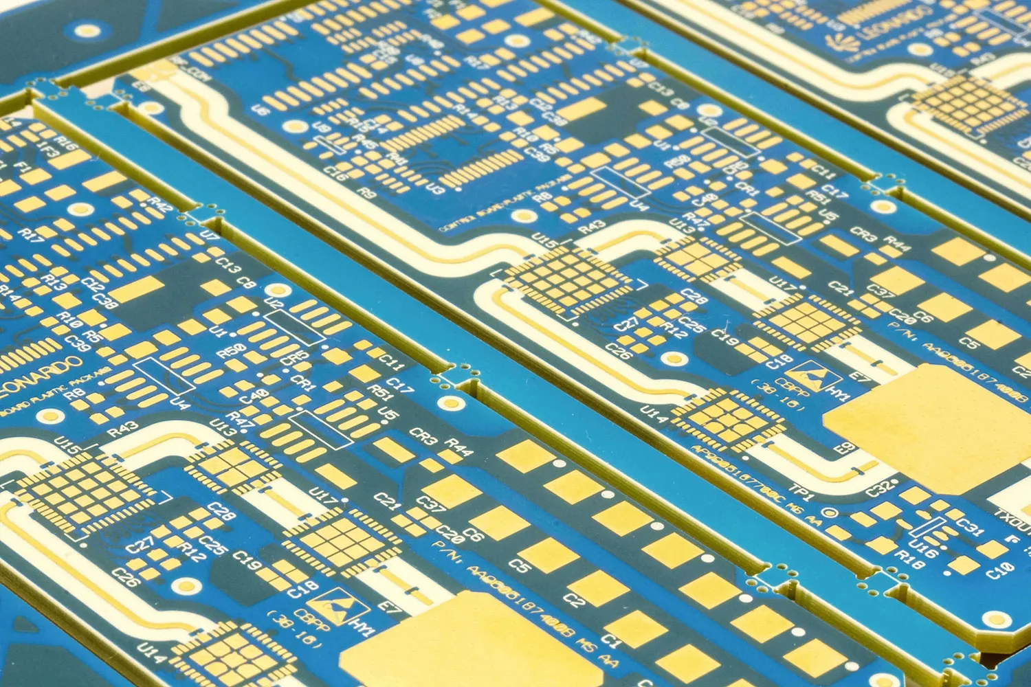
An engineering guide to low-loss PCB laminates for high-frequency ultrasound. Compare materials on dielectric loss (Df) and Dk to optimize signal integrity above 30 MHz.
A1: AIVON provides end-to-end high-frequency PCB fabrication services, including multilayer board manufacturing, precision impedance control, laser drilling, surface finishing (ENIG, OSP, etc.), and strict quality inspections. We support boards for RF, microwave, 5G, and other high-speed applications, ensuring signal integrity and reliability.
A2: Choosing the right material is critical for signal performance. High-frequency PCBs typically use low-dielectric, low-loss substrates such as Rogers, Taconic, or PTFE-based laminates. Key parameters include dielectric constant (Dk), dissipation factor (Df), thermal stability (Tg), and moisture absorption. Material selection should match your application’s frequency, speed, and environmental requirements.
A3: To ensure optimal performance:Control trace impedance precisely and maintain consistent spacing. Minimize signal path length and avoid unnecessary vias. Use ground planes and shielding to reduce interference. Select low-loss materials and proper layer stacking. Consider thermal management for high-power circuits.


