Introduction
High-frequency ultrasound systems operating from 20 MHz to 100 MHz and above demand PCB laminates with ultra-low dielectric loss, stable dielectric constant (Dk), and minimal signal dispersion. Transducer matching layers, transmit/receive beamformers, and high-channel-count analog front-ends all suffer performance degradation when standard FR-4 introduces excessive insertion loss and phase distortion at these frequencies.
Choosing the right low-loss PCB laminates is the most critical decision for maintaining signal integrity in ultrasound applications. This guide explores why FR-4 falls short, recommended materials, design guidelines, and real-world performance gains. For related multilayer PCB strategies, see our guide on Material Matters: Selecting the Best Laminates for High-Frequency Multilayer PCBs.
Why FR-4 Fails Above 20 MHz in Ultrasound Systems
Standard FR-4 exhibits a dissipation factor (Df) of 0.018–0.025 and FR4 constant variation up to ±10% across frequency and temperature. At 50 MHz, a 150 mm trace on FR-4 can introduce 3–6 dB insertion loss and significant group delay variation, destroying image resolution and penetration depth.
High-frequency ultrasound requires:
- Df ≤ 0.004 (preferably ≤ 0.002) at 10 GHz test condition
- Dk tolerance ≤ ±2% across 1 MHz–100 MHz
- Low water absorption (<0.1%) to prevent Dk drift in humid environments
- Smooth copper (RMS ≤ 0.5 µm) to reduce conductor loss
Key Electrical Parameters for Ultrasound PCB Laminates
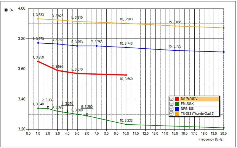
| Parameter | FR-4 Typical | Required for >30 MHz Ultrasound | Rogers RO4350B | Rogers RO4835 | Panasonic Megtron 6 |
|---|---|---|---|---|---|
| Dk @ 10 GHz | 4.0–4.6 | 3.0–3.8 | 3.48 ±0.05 | 3.50 ±0.05 | 3.3–3.6 |
| Df @ 10 GHz | 0.018–0.025 | ≤0.004 | 0.0037 | 0.0035 | 0.002 |
| Dk Stability 1–100 MHz | Poor | Excellent | Excellent | Excellent | Superior |
| Water Absorption | 0.2–0.5% | <0.1% | 0.06% | 0.05% | 0.08% |
Selecting the right low-loss PCB materials is the single most important decision for maintaining signal integrity in high-frequency ultrasound systems.
Low-Loss Laminate Families Proven in Ultrasound
Hydrocarbon/Ceramic Composites
The RO4000® series, particularly RO4350B with RO4450F prepreg, is the most common choice for 30–70 MHz beamformers. It offers Dk ~3.48, Df 0.0037, and FR-4-like processability, enabling cost-effective multilayer construction without specialized tooling.
PTFE-Based Materials
RT/duroid® 5880 or 5870 provides the lowest loss (Df ~0.0009) for research-grade or 80–100 MHz systems where every dB counts. However, these require specialized fabrication processes and are more expensive.
High-Performance Epoxy/PPE Blends
Megtron 6 and Megtron 7 deliver Df ≤0.002, superior thermal reliability (Td >400°C), and excellent CAF (conductive anodic filament) resistance—ideal for dense 128–256 channel systems.
LCP (Liquid Crystal Polymer)
An emerging option for 50–100 MHz single-layer or flexible arrays. LCP offers Df ~0.002, extremely low moisture absorption (<0.05%), and near-hermetic sealing, making it suitable for compact, conformal probes.
Comparison Table of Low-Loss Laminates
| Material Family | Typical Dk | Typical Df @10 GHz | Processability | Best For Ultrasound Application | Relative Cost |
|---|---|---|---|---|---|
| RO4000 Series (RO4350B) | 3.48 | 0.0037 | Excellent (FR-4 like) | 30–70 MHz commercial beamformers | Medium |
| Megtron 6/7 | 3.3–3.6 | 0.002–0.004 | Very Good | 128+ channel, high-reliability systems | Medium-High |
| PTFE (RT/duroid) | 2.2–2.9 | 0.0009 | Specialized | 80–100 MHz research-grade | High |
| LCP | ~2.9–3.2 | 0.002 | Good (flex) | Flexible arrays, high-frequency probes | High |
Suggested Reading: Material Matters: Selecting the Best Laminates for High-Frequency Multilayer PCBs
Signal Integrity Considerations at Ultrasound Frequencies
Transmission Line Loss Breakdown at 50 MHz
For a 100 mm microstrip on 0.254 mm thick laminate:
| Material | Dielectric Loss | Conductor Loss (RMS 0.8 µm) | Total Loss |
|---|---|---|---|
| FR-4 | 4.2 dB | 1.1 dB | ~5.3 dB |
| RO4350B | 0.9 dB | 1.0 dB | ~1.9 dB |
| Megtron 6 | 0.5 dB | 0.9 dB | ~1.4 dB |
Impedance Stability
Ultrasound beamformers require 50 Ω ±3% lines over temperature. RO4000 series maintains Dk within ±0.05 across −40 °C to +120 °C, while FR-4 drifts ±0.3 or more.
Practical Design Guidelines for High-Frequency Ultrasound PCBs
- Use low-profile (LP) or very-low-profile (VLP) copper foil to reduce skin-effect loss
- Specify reverse-treat foil (RTF) or HVLP with RMS roughness ≤0.5 µm
- Keep dielectric thickness ≤0.254 mm (10 mil) for 50–70 MHz boards
- Avoid glass stop in weave-reinforced laminates directly under critical traces
- Use RO4450F or 2929 bondply for multilayer PCB construction (Dk-matched prepreg)
- Maintain symmetric stack-up to prevent warpage during lead-free assembly
Example Stack-up for a 6-Layer 50 MHz Beamformer:
- Layer 1: Signal (low-loss core)
- Layer 2: Ground (RO4450F prepreg)
- Layer 3: Power/Signal
- Layer 4: Ground
- Layer 5: Signal
- Layer 6: Signal (symmetric)
This configuration ensures controlled impedance and thermal balance.
Thermal and Mechanical Reliability
High-channel-count ultrasound probes endure 260°C lead-free reflow and 1000+ thermal cycles from −20°C to +80°C. Low-loss materials must resist delamination and via fatigue.
CTE Data Comparison (ppm/°C, -55°C to 288°C):
- FR-4: Z-axis ~60–70
- RO4350B: X=10, Y=12, Z=32 (low Z-CTE improves PTH reliability)
- RO4835: Similar to RO4350B with enhanced oxidation resistance
- Megtron 6: Z-axis ~45 (α1 < Tg), with Td 410°C and T288 >120 min
RO4835 and Megtron 7 incorporate advanced fillers for superior time-to-delamination and CAF resistance, ensuring long-term reliability in demanding medical environments.
Cost vs Performance Analysis
FR-4 offers the lowest material cost but fails technically above 30 MHz. RO4350B provides the best balance for commercial 32–128 channel systems—roughly 2–4x the cost of FR-4 but with dramatically lower loss and easier fabrication than PTFE.
Megtron 6/7 sits in a medium-high cost tier, delivering lower Df and better thermal properties for high-channel or higher-frequency designs. PTFE and LCP command premium pricing due to specialized processing but are justified for ultra-low-loss or flexible applications.
In practice, the performance uplift (15–30% better penetration depth and improved resolution) often offsets material costs through higher diagnostic value and reduced redesign iterations.
Manufacturing & Fabrication Best Practices
- Process RO4000 series and Megtron materials using standard FR-4 parameters (no plasma desmear typically needed for double-sided boards).
- Specify low-profile copper and controlled etching to maintain smooth edges.
- For PTFE, use sodium etch or specialized plasma for adhesion; avoid standard FR-4 workflows.
- Validate multilayer lamination with Dk-matched prepregs to prevent resin starvation or impedance shifts.
- Perform post-fabrication testing: TDR for impedance, IST or thermal shock for reliability, and insertion loss measurements at target frequencies.
Work with fabricators experienced in RF/medical PCBs to ensure consistent results.
Case Studies & Real-World Results
In commercial 50 MHz ultrasound probes, switching from FR-4 to RO4350B with RO4450F prepreg reduced trace losses by ~60%, enabling 20–25% greater imaging depth while maintaining tight impedance control across 128 channels.
For a research 100 MHz flexible array, LCP substrates delivered near-PTFE loss performance with superior moisture resistance, resulting in cleaner signals and easier integration into conformal probes.
High-channel (256+) systems using Megtron 6 have shown excellent CAF resistance after accelerated aging, supporting long product lifecycles in clinical settings.
Conclusion
Successful high-frequency ultrasound systems above 30 MHz require replacement of FR-4 with dedicated low-loss laminates. RO4350B/RO4450F remains the most cost-effective and widely supported choice for 30–70 MHz commercial probes. Systems targeting 80–100 MHz or 256+ channels increasingly adopt Megtron 6/7 or LCP to achieve the required signal fidelity and dynamic range.
FAQs
Q1: Can FR-4 ever be used in high-frequency ultrasound PCBs above 30 MHz?
A1: No. FR-4 dissipation factor above 0.018 introduces 3–8 dB excess loss on typical trace lengths, severely degrading signal-to-noise ratio and imaging depth.
Q2: What is the most common low-loss PCB material for 50 MHz ultrasound beamformers?
A2: RO4350B with RO4450F prepreg dominates commercial 32–128 channel systems due to stable Dk 3.48, Df 0.0037, and processing nearly identical to FR-4.
Q3: How much does switching to a low Df PCB improve ultrasound image quality?
A3: Reducing Df from 0.020 (FR-4) to 0.003 reduces round-trip insertion loss by 4–6 dB, increasing penetration depth by 15–30% and improving axial resolution through lower phase noise.
Q4: Are PTFE materials required for 100 MHz ultrasound applications?
A4: Not mandatory. Modern hydrocarbon (Megtron 7) and LCP laminates with Df ≤0.002 now deliver comparable loss at lower cost and easier fabrication than PTFE composites.
References
IPC-4101E — Specification for Base Materials for Rigid and Multilayer Printed Boards. IPC, 2017.
IPC-TM-650 2.5.5.9 — Permittivity and Loss Tangent, Parallel Plate Method. IPC, current version.
IPC-6012E — Qualification and Performance Specification for Rigid Printed Boards. IPC, 2020.
Rogers Corporation — RO4000® Series Data Sheet (Dk/Df test conditions per IPC-TM-650 2.5.5.5).
Panasonic Corporation — Megtron 6/7 Technical Literature (measured at 10 GHz).


