Overview
A varistor provides overvoltage protection and voltage clamping in electronic circuits. The device is a nonlinear resistor whose resistance changes with applied voltage. Below are the main functions and practical considerations when using varistors.
Primary Functions
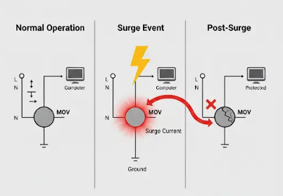
1. Overvoltage protection: A varistor is a nonlinear resistor whose resistance varies with voltage. When the circuit voltage exceeds the varistor's rated voltage, the varistor transitions to a low-resistance state, absorbing and dissipating the excess energy and limiting surge current to a safe range. This protects other components in the circuit from damage caused by overvoltage.
2. Voltage clamping and stabilization: Because a varistor's resistance changes with voltage, it can provide a degree of voltage clamping. When the circuit voltage varies significantly, the varistor automatically adjusts its resistance to limit peak voltages. This helps maintain stable operation of other components and prevents problems caused by voltage fluctuations.
3. Pressure sensing: The varistor is described here as a device that works based on a piezoelectric-like effect and can be used in pressure-sensing applications. In some cases, measuring changes in the varistor's resistance can be used to infer applied force or pressure. This is useful in certain industrial and control applications such as pressure sensors and force sensors.
Varistor Behavior with Switching Power Supply Input Spikes
When the AC input to a switching power supply is subject to high-voltage transient spikes, for example from nearby inductive switching or lightning, a varistor can switch from a high-resistance off state to a low-resistance conducting state almost instantly. A large current flows briefly through the varistor, absorbing, clipping, and limiting the high-voltage spike so that the input voltage is brought back to a safe level. If the current through the varistor is excessive, a series fuse may blow, preventing fatal damage to the switching power supply.
Varistor Testing Methods
Varistors can be tested using the following methods:
1. Resistance measurement: Use a multimeter or other appropriate instrument. Set the meter to a suitable resistance range and connect the probes across the varistor. The measured resistance can help determine if the varistor is functional. If the measured resistance is close to the varistor's expected value under test conditions, the device is likely normal. If the resistance deviates significantly or shows open circuit, the varistor may be damaged.
2. Visual inspection: Examine the varistor for visible signs of damage such as cracking, charring, deformation, or other abnormalities. Use a magnifier or microscope to inspect surface details for possible issues.
3. Functional test in a test circuit: Place the varistor in a suitable test circuit and perform operational testing. For example, in an overvoltage protection circuit, apply an input voltage above the varistor's rated voltage and observe whether the varistor conducts and effectively limits the overvoltage. This can be done in analog or digital test setups.
Before performing any tests, always disconnect the circuit power and take appropriate safety precautions to prevent hazards.