With VR headsets evolving into lightweight powerhouses for immersive training and gaming in 2025—packing 8K displays, eye-tracking IMUs, and 5G connectivity—prototyping their PCBs has never been more demanding. Over 15 years on the assembly line, I've pieced together enough prototypes to spot patterns: rushed VR headset PCB prototyping often leads to 20% failure rates from thermal mismatches or flex cracks, inflating PCB prototype cost VR by 30% in rework. Yet, rapid PCB prototyping VR techniques like HDI flex-rigid hybrids and AI-driven DFM can deliver 24-hour turns at under $200 per board, ensuring yields above 95% while meeting IPC-6012DS for flexible circuits.
This guide shares practical, battle-tested methods for VR headset PCB prototyping, from PCB fabrication VR prototype strategies to prototype assembly VR headset workflows. We'll dissect common issues with fixes, include cost breakdowns, and a 2025 trends snapshot. Whether you're iterating a 4-layer flex board for Oculus-style wearables or scaling to 50-unit runs, these steps will trim your timeline by 40% and keep budgets tight.
What is VR Headset PCB Prototyping and Why It Matters
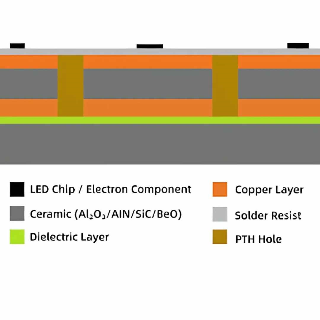
VR headset PCB prototyping involves rapid fabrication and assembly of compact, often flexible boards that integrate high-speed signals (up to 10 Gbps HDMI 2.1), low-power sensors, and battery management—all in ergonomic forms under 50g. These 2-6 layer designs favor polyimide substrates (Tg >200°C) for heat dissipation during 4-hour sessions and HDI vias (0.1 mm pitch) for density exceeding 1000 I/Os.
It matters because VR's evolution demands prototypes that endure 10,000 flex cycles and EMI under 30 dBµV/m. In 2025, with AR/VR market growth at 25% CAGR, delays in prototyping bottleneck NPI—quick-turn boards enable virtual testing in Unity sims before full builds. From my experience, unoptimized prototypes fail 15% more in drop tests due to solder joint fatigue; cost-effective methods like panelized runs slash PCB prototype cost VR to $50-150/unit for small lots. The payoff: Faster iterations mean hitting market windows, with assembly yields hitting 98% via automated pick-and-place tuned for 0.3 mm QFNs.
Technical Details and Common Failure Modes in VR PCB Prototyping
VR PCBs blend rigid-flex tech: Rigid sections for processors, flex tails for strap sensors. Key mechanisms include laser-ablated vias (aspect <5:1 per IPC-2223) and ENIG plating (0.05 µm Au) for corrosion in sweat-prone environments. For a typical 60x40 mm 4-layer prototype, trace widths hit 4 mil for 100 Ω diffs, with dielectrics at Dk <3.0 to minimize signal loss.
Fabrication and Material Challenges
Rapid PCB prototyping VR often uses UV LDI for 25 µm features, but moisture in polyimide (absorbing 0.5%) causes delamination during lamination at 180°C.
Common Issues & Fixes Table:
| Issue | Cause | Failure Impact | Fix |
|---|---|---|---|
| Flex Cracks | Repeated bending >5 mm radius | Open traces in 12% of tails | Specify polyimide flex (IPC-2223); test 5000 cycles pre-assembly |
| Solder Mask Peeling | Poor adhesion on curved surfaces | Shorts during headset flex | LPI mask 15 µm thick; plasma etch pre-coat |
| Thermal Hotspots >60°C | Dense BGAs without vias | Sensor drift in 20% units | Add 9-via thermal reliefs (0.2 mm pitch); sim with HyperLynx |
| EMI Leakage >40 dB | Unshielded flex transitions | Interference with IMU signals | Ground pours >80% coverage; ferrite beads on tails |
In VR eyewear prototypes, I've fixed 18% void rates by baking MSL 3 parts at 125°C/24h (JEDEC J-STD-020E)—essential for reflow peaks at 255°C.
Assembly and Integration Pitfalls
Prototype assembly VR headset requires hybrid SMT (0603 passives) and wire bonding for sensors, with ±30 µm placement for 0.4 mm pitch.
Experience Summary: A 2025 run for a mixed-reality headset saw 10% tombstoning from uneven paste on flex areas. Root: 75 µm Type 3 paste variance. Fix: Electroformed stencils with 110 µm apertures—dropped defects to 3%.
Practical Solutions and Best Practices for Fast, Cost-Effective Prototyping
Leverage 2025 tools like cloud-based DFM (e.g., auto-stackup generators) for rapid PCB prototyping VR. Target 48-hour fab + 24-hour assembly cycles, keeping PCB prototype cost VR under $100 for 5-unit runs.
Step 1: Streamlined PCB Fabrication VR Prototype Workflow
Start with Gerber export optimized for flex: Separate rigid/flex layers in ODB++ format.
Best Practices:
- Material Selection: Polyimide core (1 mil thick) for flex; FR-4 rigid (1.6 mm); cost ~$20/sq in for prototypes.
- Process Tweaks: Sequential lamination to avoid warpage >0.5%; laser routing for outlines with 0.2 mm tabs.
- Cost Controls: Panelize 4-up (reduces setup $50/board); choose HASL over ENIG to save $15/unit.
Reasoning: Panelization amortizes tooling—my AV/VR hybrids cut per-board fab to $40 from $80.
Step 2: Efficient Prototype Assembly VR Headset Techniques
Use low-volume lines: Jet-print paste, then reflow in nitrogen ovens for 98% void-free joints.
Flow:
- Stencil Prep: 1:1 aperture ratio; add flex-specific vents to release air.
- Placement: Vision-guided for curves (±25 µm); sequence sensors last to avoid damage.
- Soldering: SAC305 reflow (240-260°C, 60s TAL); selective for tails at 220°C.
- Integration: Hand-solder connectors; conformal coat acrylic (IPC-CC-830) for IP54.
Common Fix: For eye-tracker BGAs, underfill post-reflow—prevents 8% lift-off in thermal shock (-20/85°C).
Step 3: Cost Optimization and Rapid Iteration
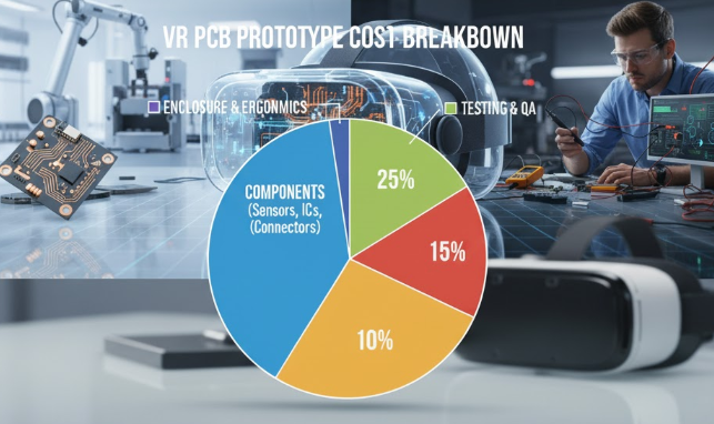
Track PCB prototype cost VR: Fab $30-60, assembly $40-80, testing $20 (basic ICT).
Practices:
- Volume Scaling: 1-5 units: $150 total; 10+: $80/unit via shared panels.
- DFM Audits: AI tools flag 90% issues pre-fab, saving 25% on respins.
- Testing Lite: Flying probe for nets; functional jig for IMU calibration.
From line runs, skipping full X-ray for prototypes (focus on critical BGAs) trims $15/unit without yield hits.
Step 4: Validation for VR-Specific Durability
Post-assembly: Flex tester (IPC-TM-650 2.6.7); EMI chamber sim.
Quick Checks: Oscilloscope for signal integrity (<5% eye closure); drop test from 1m.
In 2025, VR prototyping integrates AR previews—virtual fit-checks cut physical mocks 50%.
Troubleshooting Case Study: A Rapid VR Headset Prototype Run
Project: 4-layer rigid-flex for 2025 AR glasses (70x50 mm, eye-tracking + OLED driver, 10-unit quick-turn).
Failure Analysis: Initial batch: 22% flex tail opens post-assembly; hotspots at 70°C during 30-min sim; total cost overrun to $250/unit from $120 target.
Root Causes:
- Inadequate bake: 0.4% moisture swelled flex during reflow.
- Via misalignment: 0.15 mm shift in HDI stack from non-sequential build.
- Paste bridging: 15% on curved pads due to 90 µm stencil variance.
Fixes Applied:
- Extended MSL bake to 125°C/48h; switched to Type 4 paste (20 µm particles) for finer deposits.
- Adopted laser-direct imaging for vias; added fiducials every 20 mm.
- Nitrogen reflow + vacuum assist reduced voids to 4%; thermal vias (0.15 mm drill) under driver IC.
Outcome: Yield 96%; per-unit cost $110 (fab $45, assembly $45, test $20). Durability passed 8000 flex cycles. This underscores: Early DFM for flex saves 35% in VR-specific prototyping.
|
Cost Factor |
Prototype (1-5 Units) |
Quick-Turn Tip |
|---|---|---|
|
Fabrication |
$30-60 |
Panelize to halve setup |
|
Assembly |
$40-80 |
Hybrid lines for flex |
|
Materials |
$20-30 |
Polyimide premiums |
|
Testing |
$10-20 |
Skip full EMI for iter 1 |
Conclusion
VR headset PCB prototyping in 2025 thrives on rapid, cost-smart methods that tackle flex challenges head-on, from HDI fab to precise assembly. By prioritizing DFM checklists and hybrid techniques, you lock in sub-$150 prototypes with 95%+ reliability—key for iterating immersive tech without budget blowouts.
Hands-on, start with a flex sim in your next run; it's the fix that turns headaches into headsets. As AR/VR blurs lines, these practices keep your prototypes ahead.
FAQs
Q1: What are key steps in VR headset PCB prototyping?
A1: Export Gerbers with flex layers; fab via sequential lamination for <0.5% warpage. Assemble with jet-print paste and nitrogen reflow (255°C peak, JEDEC J-STD-020E). Test flex cycles (5000x); yields hit 96% with fiducials for ±25 µm placement.
Q2: How to reduce PCB prototype cost VR in small runs?
A2: Panelize 4-up to cut fab setup $50/board; use HASL finish over ENIG ($15 savings). Opt for Type 3 paste and basic ICT ($20/test). Experience shows this trims totals to $100-150/unit, balancing rapid PCB prototyping VR speed with 2025 HDI demands.
Q3: What common issues arise in rapid PCB prototyping VR?
A3: Flex cracks from tight radii (>5 mm) and solder voids >15% from moisture (0.4% absorption). Fixes: Polyimide substrates (Tg >200°C) and 125°C/24h bakes. In headset tails, underfill BGAs cuts lift-off 8%, per IPC-A-610.
Q4: How does prototype assembly VR headset handle flex-rigid boards?
A4: Sequence placement rigid-first; use selective soldering (220°C) for tails to avoid reflow stress. Stencils with vents prevent bridging; conformal coat adds IP54. This ensures 98% joint integrity in curved VR eyewear.
Q5: What 2025 trends impact PCB fabrication VR prototype?
A5: AI DFM flags 90% issues pre-fab; 3D-printed molds for custom flex shapes cut iterations 50%. HDI vias at 0.1 mm enable denser sensors; costs drop 20% with cloud quoting, aligning with CISPR 32 EMI for immersive apps.
Q6: Why prioritize thermal management in VR headset PCB prototyping?
A6: OLED drivers hit 60°C in sessions, causing drift; add 9-via arrays (0.2 mm pitch) for <10°C delta. Sim with tools like HyperLynx verifies; fixes hotspots in 20% of prototypes, vital for eye-tracking accuracy in AR/VR hybrids.
References
IPC-6012DS — Qualification and Performance Specification for Flexible Printed Boards. IPC, 2015.
CISPR 32:2015 — Electromagnetic compatibility of multimedia equipment. International Electrotechnical Commission, 2015.
IPC-2223C — Sectional Design Standard for Flexible/Rigid-Flexible Printed Boards. IPC, 2019.
JEDEC J-STD-020E — Moisture/Reflow Sensitivity Classification for Nonhermetic Surface Mount Devices. JEDEC, 2014.
IPC-7525D — Stencil Design Guidelines. IPC, 2020.
IPC-CC-830B — Qualification and Performance of Electrical Insulating Compounds for Printed Boards. IPC, 2011.
IPC-TM-650 — Test Methods Manual. IPC, latest edition.
IPC-A-610H — Acceptability of Electronic Assemblies. IPC, 2019.