What Constitutes Vibration Analysis for PCB Components?
Vibration analysis involves a thorough examination of how mechanical vibrations influence both the structural integrity and the operational functionality of electronic components situated on a Printed Circuit Board (PCB). These vibrations can originate from diverse external sources, including active machinery, transportation systems, or various environmental factors. Their consequences can range from critical issues like solder joint fatigue, component detachment, to significant signal interference. By meticulously analyzing these vibratory effects, engineers gain the ability to anticipate potential failures and devise robust solutions to mitigate associated risks.
In this comprehensive guide, we will dissect the pivotal as pects of vibration analysis, addressing its importance, effective testing methodologies, and strategic approaches for efficient vibration isolation. Our discussion will specifically incorporate terms such as "design PCB for vibration isolation," "flexurally suspended body for PCBs," "electronic PCB boxes," and "vibration isolation PCB test" to provide precise, targeted guidance for your projects.
Why Is Vibration Analysis Crucial for Effective PCB Design?
PCBs serve as the fundamental backbone for the vast majority of electronic devices, and their embedded components are often inherently delicate. Vibrations can induce considerable mechanical stress, which in turn leads to the formation of micro-cracks in solder joints or even the complete failure of critical components like capacitors or various connectors. In high-stakes applications—consider aerospace guidance systems or life-sustaining medical devices—a single failure triggered by vibration can have potentially catastrophic repercussions.
For example, within automotive electronics, PCBs are subjected to incessant vibrations stemming from engine operation and variable road conditions. Research indicates that a significant proportion, up to 20%, of electronic failures in vehicles are directly attributable to mechanical stress caused by vibrations. By performing diligent vibration analysis, engineers can accurately pinpoint resonant frequencies—specific vibration frequencies at which the PCB or its components amplify the shaking effect—and consequently tailor designs to avoid these destructive resonances, thereby preventing damage.
Furthermore, vibration analysis is instrumental in meeting stringent industry standards. Numerous sectors mandate that PCBs successfully pass rigorous validation tests, such as MIL-STD-810 for military-grade applications, which includes comprehensive vibration testing across a broad frequency range from 5 Hz to 2000 Hz. Comprehending these critical requirements early in the design phase translates into substantial savings in both time and cost during the subsequent production stages.
What Key Factors Influence PCB Vibration Susceptibility?
Several interdependent factors dictate how vibrations affect a PCB. A clear understanding of these elements is vital for designing more resilient and dependable circuit boards:
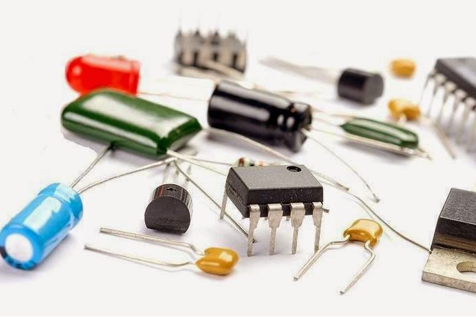
● Component Placement: Components that are heavy or possess considerable height, such as power transformers or large electrolytic capacitors, exhibit greater susceptibility to vibration-induced stress. Strategically positioning these near robust mounting points or incorporating additional structural supports can significantly reduce their movement and stress.
● Board Material: The intrinsic material of the PCB, typically FR-4 with a standard thickness of 1.6 mm, directly influences its stiffness. Utilizing thicker boards (e.g., 2.0 mm) or employing alternative, more rigid materials like polyimide can offer enhanced resistance to bending and flexing under vibratory loads.
● Mounting Method: The specific manner in which the PCB is secured within its enclosure plays a pivotal role. Rigid mounting configurations can directly transmit vibrations to the board, whereas flexible or isolated mounting solutions are designed to absorb a portion of the vibratory energy, thereby protecting the PCB.
● Operating Environment: Environments characterized by high vibration levels, such as those in proximity to heavy industrial machinery, necessitate considerably more robust designs compared to electronic equipment intended for static office settings.
How to Design PCBs for Effective Vibration Isolation
One of the most impactful strategies for safeguarding electronic components is to proactively design a PCB for vibration isolation. This approach fundamentally aims to minimize the transfer of mechanical energy directly to the board and its constituent parts. Here are several practical recommendations:
1. Employ Damping Materials
Integrate damping materials, such as silicone pads or rubber grommets, between the PCB and its designated mounting points. These materials effectively absorb vibration energy, thereby reducing the amplitude of oscillations that ultimately reach the circuit board. For example, utilizing rubber standoffs with a typical damping coefficient of approximately 0.2 can diminish vibration transmission by up to 50% at specific critical frequencies.
2. Optimize Component Layout
Position sensitive or heavy components away from areas that experience high vibration amplitudes, which are often located near the center of symmetrically mounted PCBs. Secure larger components using specialized adhesives or robust brackets to prevent their detachment during exposure to high-frequency vibrations (typically above 100 Hz).
3. Reinforce the PCB's Structural Integrity
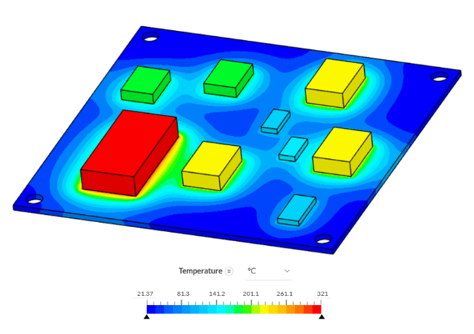
Introducing stiffeners or increasing the overall board thickness can effectively reduce flexural bending. A PCB with a thickness of 2.0 mm, as opposed to the standard 1.6 mm, can reduce deflection under vibration by approximately 30%, a finding often supported by detailed finite element analysis studies.
4. Implement Isolation Mounting Hardware
Specialized isolation mounts, such as spring-loaded fasteners or elastomeric isolators, can significantly curtail vibration transfer. These mounts are most effective when their characteristics are carefully tuned to the anticipated vibration frequency range of the operational environment, often between 10 Hz and 500 Hz for typical industrial applications.
Exploring the Flexurally Suspended Body: An Advanced PCB Mounting Strategy
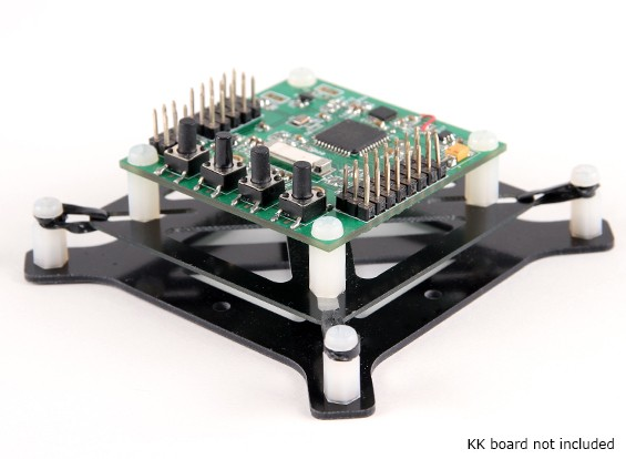
A flexurally suspended body refers to an innovative PCB mounting design where the circuit board is intentionally configured to allow for controlled bending or flexing. This controlled movement serves to absorb significant amounts of vibration energy. This advanced technique is frequently employed in demanding applications where a purely rigid mounting scheme would transfer an unacceptable level of stress directly to the PCB.
In this sophisticated method, the PCB is supported by flexible elements or specialized springs at strategically chosen points. This allows the board to move slightly without experiencing damaging stresses or fractures. This type of setup effectively lowers the natural resonant frequency of the entire system, often to below 20 Hz, making it far less susceptible to resonating with typical environmental vibrations (which are usually above 30 Hz). For example, in aerospace electronics, a flexurally suspended body can provide crucial protection to PCBs from the intense vibrations encountered during launch sequences, where acceleration levels can frequently surpass 10g.
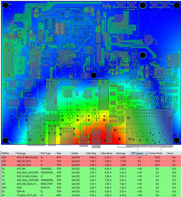
To implement such a design, engineers commonly utilize finite element modeling to accurately predict how the PCB will flex under various dynamic loads. The overarching objective is to ensure that the degree of bending does not exceed the material’s yield strength, which for standard FR-4 boards is typically around 70 MPa. This highly analytical approach requires precise calculations but can considerably extend the operational lifespan of a PCB in environments characterized by high vibration.
Electronic PCB Boxes: Essential Enclosures for Enhanced Protection
Electronic PCB boxes, or protective enclosures, play a profoundly important role in shielding circuit boards from external vibrations. A thoughtfully engineered enclosure not only provides defense against dust and moisture but also acts as the primary barrier against mechanical stress.
When considering or designing an enclosure, several critical factors warrant attention:
● Material Selection: Enclosures fabricated from metallic materials, such as aluminum (with a typical density of 2.7 g/cm³), generally offer superior vibration damping characteristics compared to plastic alternatives, owing to their greater mass and inherent stiffness.
● Internal Mounting Points: Employ shock-absorbing mounts positioned strategically inside the enclosure to effectively isolate the PCB from any vibrations transmitted through the enclosure itself. These specialized mounts can reduce transmitted vibration by as much as 40% at frequencies above 50 Hz.
● Effective Sealing: Ensure the enclosure is sealed meticulously to prevent any internal rattling, which can inadvertently amplify vibrations within the box and transfer them to the PCB.
Custom-designed enclosures can also incorporate internal ribs or dedicated damping layers to further diminish the effects of vibration. For applications demanding exceptionally high reliability, some enclosures are engineered and rigorously tested to withstand vibration levels up to 5g across a broad frequency spectrum of 10 Hz to 500 Hz.
Proven Vibration Isolation PCB Test Techniques
Rigorous testing constitutes an absolutely critical phase in vibration analysis. It is essential for validating the design and confirming that the PCB can reliably endure real-world operational conditions. Here are some commonly employed vibration isolation PCB test methods:
1. Shaker Table Testing
This method involves securely mounting the PCB onto a specialized shaker table that can accurately simulate various vibration frequencies and amplitudes. Tests are frequently conducted over a wide range, typically from 5 Hz to 2000 Hz, with acceleration levels reaching up to 20g. These parameters are designed to mimic the severe conditions found in automotive or aerospace environments. The primary objective is to pinpoint resonant frequencies and observe any instances of component failure.
2. Modal Analysis
Modal analysis employs advanced sensors, such as accelerometers, to precisely measure the natural frequencies and characteristic mode shapes of the PCB. By thoroughly understanding how the board deforms and responds under vibratory stress, engineers can refine the design to proactively avoid dangerous resonance conditions. For instance, a typical PCB might exhibit a first natural frequency around 60 Hz, which should be sufficiently far removed from the dominant vibration frequency prevalent in its intended operating environment.
3. Fatigue Testing
This long-duration test subjects the PCB to an extended series of repeated vibration cycles, meticulously simulating years of operational use. Fatigue testing helps in predicting when solder joints or specific components might succumb to failure due to material fatigue. A common benchmark involves testing for 10 million cycles at a precisely defined frequency to definitively ascertain the board's long-term durability.
Best Practices for Designing Vibration-Resistant PCBs
To synthesize the wealth of design and testing insights, here are some overarching best practices to ensure your PCB effectively withstands vibratory challenges:
● Integrate Simulation Early: Utilize advanced software tools during the initial design phase to accurately predict and analyze potential vibration effects before physical prototyping.
● Select Vibration-Tolerant Components: Choose electronic components that possess specific vibration tolerance ratings suitable for your application's expected environment.
● Secure Connectors and Cables: Ensure all connectors and associated cables are firmly secured to prevent loose connections or dislodgment under vibratory stress.
● Rigorous Prototype Testing: Consistently test prototypes under simulated worst-case scenarios to identify and resolve any latent issues prior to commencing mass production.
Conclusion: Mastering Vibration Analysis for Robust Electronics
Comprehensive vibration analysis of electronic PCB components is an absolutely vital process for guaranteeing the durability and unwavering reliability of electronic systems operating in challenging environments. By strategically concentrating on methodologies such as designing PCBs for effective vibration isolation, exploring innovative flexurally suspended body configurations, utilizing robust electronic PCB boxes, and conducting exhaustive vibration isolation PCB tests, engineers can dramatically lower the risk of premature failure.
AIVON recognizes the critical importance of producing high-quality, vibration-resistant PCBs for an expansive array of applications. Whether your project involves designing industrial machinery, advanced automotive systems, or cutting-edge aerospace technology, the systematic integration of these vibration analysis techniques into your design workflow will be instrumental in achieving long-lasting, highly dependable results. Begin implementing these strategies in your next project to comprehensively shield your electronics from the detrimental effects of vibrations.