Why Embark on Building a DIY AI Accelerator?
In recent years, the concept of edge AI—executing machine learning models directly on compact, low-power devices—has revolutionized various applications. Unlike cloud-dependent AI, edge AI processes data locally, significantly reducing latency and bolstering privacy. For hobbyists, constructing a DIY AI accelerator offers an immersive opportunity to grasp the intricacies of machine learning hardware and to experiment with frameworks like TensorFlow Lite, which is specifically optimized for microcontrollers and similar small-scale systems.
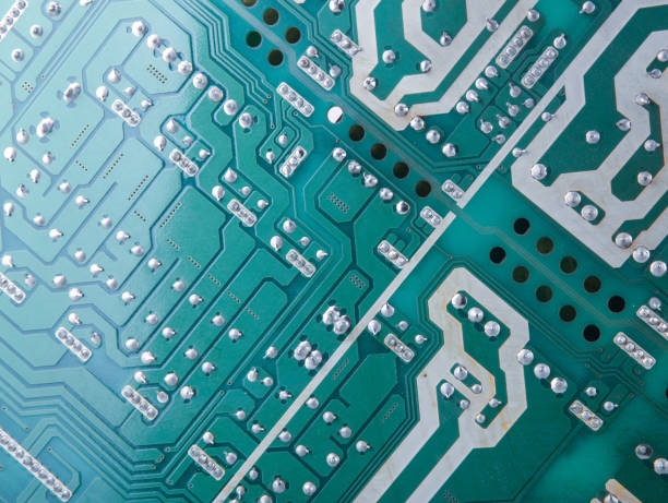
The core of such a project is a custom PCB (Printed Circuit Board). This enables you to craft a specialized circuit that precisely fulfills the unique demands of your AI accelerator, encompassing everything from power efficiency to processing velocity. By the conclusion of this guide, you will possess a clear pathway to design and assemble your personalized hardware for a range of edge AI applications.
What Essential Resources Are Needed for a Custom AI Accelerator?
Before commencing the design and construction phases, it's crucial to assemble the necessary resources. Here's a comprehensive overview of the tools, components, and fundamental skills required for a DIY AI accelerator featuring a custom PCB:
Hardware and Software Essentials
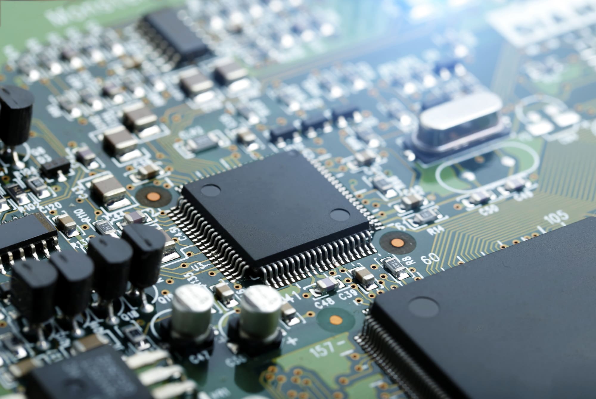
You'll need specific hardware components: a microcontroller or microprocessor capable of executing AI models (such as an ARM Cortex-M series for TensorFlow Lite), memory modules (like SRAM or flash storage), and integrated circuits for power management. For design, software tools for schematic capture and PCB layout are indispensable for creating your bespoke board.
Skills and Budget Considerations
Programming knowledge, particularly familiarity with C/C++ for microcontroller coding and TensorFlow Lite for model deployment, is key. Basic electronics skills, including soldering, fundamental circuit design, and debugging techniques, are also essential. Depending on the selection of components, expect a budget ranging from $50 to $200 for a small-scale prototype.
Demystifying AI Accelerators and Edge AI for Hobbyists
An AI accelerator is a specialized hardware unit engineered to expedite machine learning operations, such as running neural networks for image recognition or voice processing. Unlike general-purpose processors, accelerators are optimized for specific computations prevalent in AI models, like matrix multiplications. For hobbyists, constructing a DIY AI accelerator entails building a scaled-down version of this hardware, often utilizing readily available microcontrollers tailored for edge AI.
Edge AI involves deploying these machine learning models directly onto devices with constrained resources, such as sensors or IoT gadgets, rather than relying on powerful cloud-based servers. TensorFlow Lite, a streamlined variant of the widely used machine learning framework, is perfectly suited for this purpose. It can operate on devices with mere kilobytes of memory, making it an ideal choice for amateur projects.
How to Select the Right Hardware for Your DIY AI Accelerator
The choice of hardware forms the bedrock of your project. For a beginner-friendly DIY AI accelerator, prioritize microcontrollers that offer robust support for TensorFlow Lite. The 32-bit ARM Cortex-M series microcontrollers are popular choices, providing an excellent balance of computational performance and power efficiency. Seek out boards equipped with at least 256 KB of RAM and 1 MB of flash memory to comfortably manage basic AI models.
Key Hardware Specifications
When selecting your microcontroller, consider these vital specifications:
● Clock Speed: Aim for a minimum of 48 MHz to ensure adequate processing times for AI inference tasks.
● Power Consumption: Choose a chip with minimal power draw (e.g., under 100 mA at full load) for projects intended to be battery-powered.
● I/O Pins: Ensure a sufficient number of pins for connecting sensors or other peripherals, typically between 10 to 20 General Purpose Input/Output (GPIO) pins.
Beyond the microcontroller, you will require supporting components such as voltage regulators (e.g., a 3.3V regulator with a 500 mA output) and capacitors (e.g., 10 μF ceramic capacitors positioned near power pins to mitigate electrical noise) to guarantee stable power delivery.
Designing a Custom PCB for Your DIY AI Accelerator
The creation of a custom PCB is where your DIY AI accelerator truly takes on its unique character. A custom PCB allows for the seamless integration of your microcontroller, power circuits, and any additional components onto a single, compact board. Here’s a guide for hobbyists approaching custom PCB design:
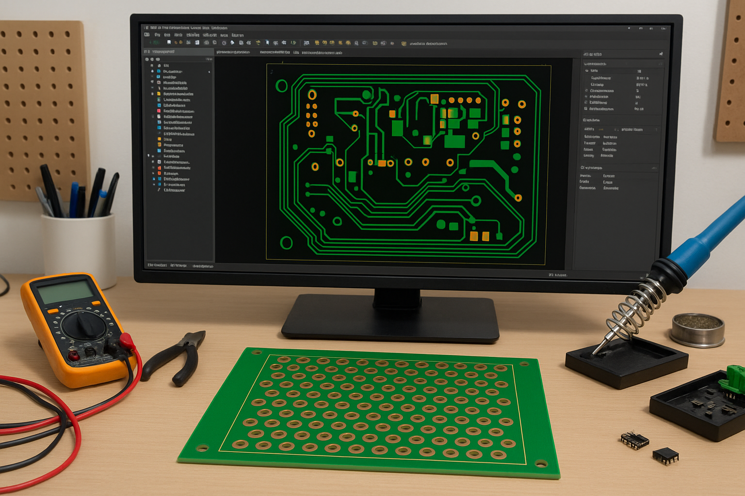
PCB Design Fundamentals and Software
Begin by mastering the foundational principles of circuit design. Your PCB must efficiently route power and signals while minimizing potential interference. Key concepts include using appropriate trace widths—for power lines, traces should be at least 0.5 mm wide to safely conduct currents up to 500 mA without overheating. Maintain signal integrity by keeping high-speed signal traces (such as those for SPI or I2C sensor data) short and distant from power lines to prevent crosstalk. Crucially, incorporate a solid ground plane on one layer of your PCB to effectively reduce electrical noise. Select a user-friendly PCB design software tool to create your schematic and subsequent layout. Start by drafting a schematic that outlines the connections between your microcontroller, power supply, memory, and peripheral components. Subsequently, transition to the layout phase, where you virtually arrange components and route traces on your board.
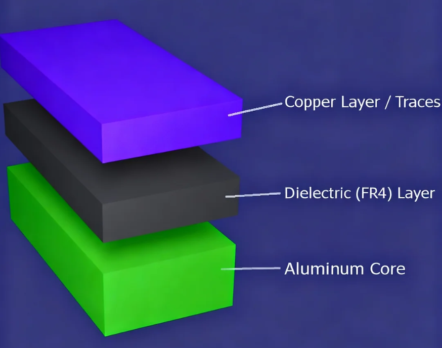
Prototyping with a Two-Layer Board
For hobbyists, a two-layer PCB offers a cost-effective and generally sufficient solution for most DIY AI accelerator projects. A typical two-layer board (1.6 mm thick with 1 oz copper) can adeptly manage the low-to-moderate current requirements characteristic of edge AI hardware. Ensure your design adheres to standard manufacturing tolerances, such as a minimum trace spacing of 0.15 mm, to avoid production complications.
Programming Your AI Accelerator with TensorFlow Lite
Once your hardware is fully prepared, the next step involves programming your DIY AI accelerator. TensorFlow Lite, being a lightweight framework optimized for microcontrollers, is an ideal choice for edge AI projects. Follow these steps to deploy a straightforward machine learning model:
Model Training and Deployment
Initiate with a basic model, such as a neural network designed for classifying sensor data (e.g., detecting motion). Utilize TensorFlow on a desktop environment to train your model, then convert it to the TensorFlow Lite format using the provided converter tool. This process significantly reduces the model's size, enabling it to fit onto devices with limited memory, often resulting in models under 100 KB. Program your microcontroller using a compatible Integrated Development Environment (IDE). Incorporate the TensorFlow Lite library into your project and upload the converted model alongside the inference code. For example, a model running on a 48 MHz microcontroller can complete inference in under 50 milliseconds for small datasets (e.g., 10 input features).
Performance Optimization
Enhance your model's performance by quantizing it to utilize 8-bit integers instead of 32-bit floating-point numbers. This optimization can reduce memory usage by up to 75% with minimal impact on accuracy. Rigorously test the model on your custom hardware to ensure it operates smoothly without exceeding the available RAM limits.
Testing and Debugging Your Custom AI Accelerator
After assembling your custom PCB and uploading your code, it’s essential to thoroughly test your AI accelerator. Connect it to a simple input, such as a temperature sensor, and verify that it correctly processes data and generates predictions. Use a multimeter to confirm voltage levels (e.g., ensuring 3.3V at the microcontroller input) and an oscilloscope to inspect signal timing if you suspect any issues.
Common problems often include power instability, which can usually be resolved by adding decoupling capacitors (e.g., 0.1 μF near each IC), and firmware bugs, which can be debugged by outputting variable values over a serial connection at 9600 baud. Continuously refine your design by adjusting the PCB layout or modifying the code based on the insights gained from your test results.
Scaling Your DIY AI Accelerator Project
Once your foundational DIY AI accelerator is operational, consider expanding its capabilities. Integrate additional sensors for more intricate tasks, such as combining motion and light data for a sophisticated smart home device. If necessary, upgrade to a more powerful microcontroller or design a four-layer PCB for superior signal routing and enhanced noise reduction. A four-layer board can effectively separate power and ground planes, thereby reducing impedance to below 0.1 ohms for high-speed signals.
You can also draw inspiration from open-source communities. Many hobbyists share their edge AI projects online, offering valuable code and schematics that you can adapt for your own DIY AI accelerator endeavors.
Essential Tips for Success in Custom PCB Design and Edge AI
To maximize the success of your project, consider these practical tips:
Strategic Design and Documentation
Begin with a simple model and minimal hardware to grasp the fundamentals before moving on to more complex designs. Meticulously review your PCB schematic and layout for any potential errors prior to manufacturing to prevent costly mistakes. Design your PCB to incorporate headers or connectors, facilitating easy upgrades or replacements of components. Maintain comprehensive documentation of all your design choices and test results, which will significantly streamline future iterations and troubleshooting.
Anticipating and Overcoming Challenges
Building a DIY AI accelerator with a custom PCB presents its own set of challenges. Limited processing power can lead to slower inference times, particularly for larger models. Overheating is another concern; ensure adequate heat dissipation by appropriately spacing components and utilizing traces with sufficient width (e.g., 1 mm for high-current paths). Finally, PCB design demands patience and persistence; be prepared for a learning curve if you are new to layout tools or soldering techniques.
Conclusion: Begin Your DIY AI Accelerator Journey
Embarking on the creation of a DIY AI accelerator with a custom PCB is an immensely stimulating and rewarding endeavor for any hobbyist passionate about machine learning hardware and edge AI. By methodically following the steps outlined in this guide—from the initial selection of appropriate hardware to advanced programming with TensorFlow Lite—you can construct a fully functional prototype tailored precisely to your specific requirements. Whether your goal is to power a smart sensor or to experiment with neural networks, the invaluable skills you acquire will unlock a myriad of innovative possibilities.
Take the crucial first step by gathering your components and outlining a simple design. With consistent patience and diligent practice, your custom PCB and AI accelerator will come to fruition, demonstrating that even hobbyists can significantly advance the frontiers of technology. Dive into the world of edge AI today and explore the endless potential of your creativity!