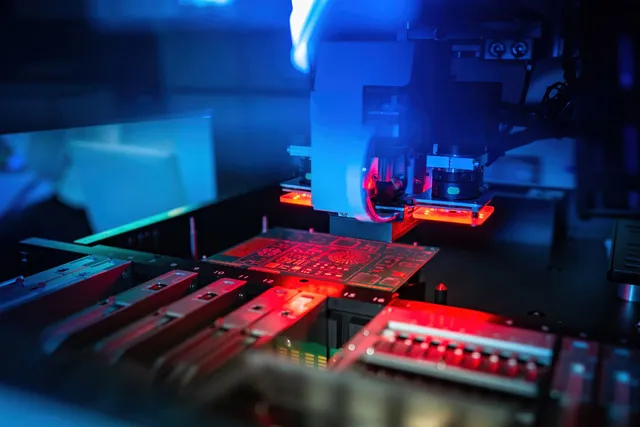
Why Is Proper Lighting Critical for PCB Automated Optical Inspection?
The foundation of effective Automated Optical Inspection (AOI) in printed circuit board (PCB) manufacturing rests heavily on appropriate illumination. Without adequate lighting, even the most sophisticated cameras and analysis software can overlook crucial flaws, such as misaligned parts, soldering imperfections, or hairline fractures. AOI systems depend on sharp, high-resolution images to compare a board against its intended design. Inadequate lighting can introduce issues like shadows, glare, or insufficient contrast, leading to erroneous defect reports or, worse, undetected problems.
Modern PCBs often feature a dense arrangement of components that vary significantly in height and material composition, posing a considerable challenge for uniform illumination. A meticulously designed lighting configuration ensures that every element on the board—from a tall capacitor to a minuscule surface-mount resistor—is clearly discernible. By skillfully applying AOI lighting methods, manufacturers can achieve substantial reductions in defect rates and significantly boost inspection precision, as evidenced by recent industry studies.
What Are the Key AOI Lighting Types Used for PCB Evaluation?
Selecting the appropriate lighting is the initial step toward enhancing your AOI system. Different illumination types fulfill distinct requirements, depending on the PCB's design and the specific flaws you aim to identify. The following are the most prevalent AOI lighting techniques employed in PCB inspection:
Coaxial Lighting
Coaxial, or on-axis, lighting directs light vertically onto the PCB surface using a beam splitter. This setup is particularly effective for examining flat, reflective areas, as it minimizes shadows and glare. It proves especially useful for identifying surface imperfections or defects on polished components. However, it may struggle with taller components that require illumination from the sides.
Ring Lighting
Ring lighting employs a circular arrangement of light sources positioned around the camera lens. This configuration provides consistent illumination from all directions, thereby reducing shadows on uneven surfaces. It is a preferred choice for general PCB inspection, especially for boards featuring components of varied heights. By adjusting its intensity, ring lighting can effectively highlight issues like missing components or misaligned solder connections.
Dome Lighting
Dome lighting generates a diffused, shadow-free illumination by reflecting light off a dome-shaped surface onto the PCB. This method excels with highly reflective or curved surfaces where glare could obscure potential defects. Dome lighting ensures uniform image quality, even on intricate board layouts, making it easier to pinpoint issues such as solder bridging or insufficient solder.
Backlighting
Backlighting positions the light source beneath the PCB, shining upwards through any transparent or semi-transparent sections. This technique is ideal for inspecting through-hole components or verifying hole alignment. It creates a sharp contrast between the board material and open spaces, clearly revealing defects like missing holes or inaccurately drilled vias.
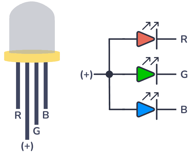
Programmable Multi-Color Lighting
Programmable lighting, often utilizing multi-color LEDs, enables dynamic adjustments during the inspection process. For instance, red light might improve contrast on certain materials, while blue light could reveal defects on others. This adaptability is invaluable for inspecting PCBs with diverse finishes and components, ensuring comprehensive defect coverage across various conditions.
How Do AOI Lighting Angles Influence Inspection Clarity?
Beyond selecting the correct lighting type, the precise angle at which light interacts with the PCB is equally vital. Strategic AOI lighting angles can accentuate specific defects that might otherwise remain unseen. Here's how different angles affect the quality of your inspection:
Low-Angle Illumination
Low-angle lighting, typically positioned at 10 to 30 degrees from the PCB surface, accentuates surface texture and variations in height. This approach is highly effective for identifying flaws such as lifted leads, "tombstoning" (where components stand upright due to uneven soldering), or irregular solder paste application. By casting shadows on raised features, low-angle lighting simplifies the detection of dimensional inconsistencies.
High-Angle Illumination
High-angle lighting, positioned between 60 to 90 degrees, delivers broad, uniform illumination across the PCB. This angle is optimal for general inspection as it minimizes shadows and ensures that flat areas are well-lit. It is frequently paired with ring or coaxial lighting to capture clear images of the board's overall layout and component placement.
Side-Angle Illumination
Side-angle lighting, set at 30 to 60 degrees, strikes a balance between low and high angles. It is particularly effective for illuminating taller components without casting harsh shadows on shorter ones. This angle helps uncover defects on component sides, such as cracks or misalignments, and is often combined with programmable lighting for adjustable intensity. Many advanced AOI systems integrate multiple angles within a single inspection cycle, dynamically adjusting angles to improve defect detection rates.
What Is the Best Way to Set Up AOI Lighting for Optimal Results?
A meticulously planned AOI lighting setup integrates the right lighting types and angles to establish a robust inspection process. Here are the crucial steps for configuring your AOI lighting system to achieve superior PCB quality control:
Initial PCB Design Evaluation
Begin by thoroughly examining the unique features of your PCB. Are there tall components that might create shadows? Does the board possess reflective surfaces that could cause glare? Understanding these factors will guide your selection of appropriate lighting types and angles. For instance, a board with varied component heights might benefit from a combination of high-angle ring lighting and low-angle side lighting.
Hardware Selection and Positioning
Invest in high-quality lighting hardware that offers flexibility. Modern AOI systems frequently employ LED arrays due to their energy efficiency, longevity, and programmability for different colors and intensities. Ensure your setup can accommodate various lighting types, such as coaxial and dome, to address diverse inspection requirements. Position lights at angles that align with your inspection objectives. For example, place low-angle lights around the inspection area's perimeter to highlight height-related defects, and use high-angle lights directly above the PCB for overall illumination. Whenever possible, integrate adjustable mounts for fine-tuning angles during testing.
Calibration and Refinement
Calibrate the intensity of your lights to achieve optimal contrast, as excessive or insufficient light can obscure details. If utilizing multi-color lighting, experiment with different wavelengths to determine which ones best accentuate specific defects. For example, a green light with a 550 nm wavelength often provides excellent contrast for solder joint inspection on standard FR4 boards. Conduct test inspections on sample PCBs to assess your lighting configuration. Look for areas where defects are missed or false positives occur, and adjust the lighting accordingly. Modern AOI software often includes tools to analyze image quality, helping you pinpoint necessary lighting adjustments. Repeat this iterative process until defect detection consistently reaches an acceptable threshold.

How Can Common AOI Lighting Challenges Be Overcome?
Even with thorough planning, AOI lighting setups can encounter difficulties. Here are some frequent issues and practical solutions:
Managing Shadows and Glare
Tall components, such as electrolytic capacitors, can cast shadows that conceal defects on nearby smaller components. Address this by using a combination of side-angle and ring lighting to illuminate around obstacles. Slightly adjusting the camera's off-axis position can also help capture hidden areas. Highly reflective surfaces, like gold-plated connectors, can produce glare that obscures details. Counter this by switching to diffused lighting, such as dome lighting, to minimize reflections. Employing polarizing filters on the camera lens can further reduce glare without compromising image quality.
Ensuring Uniformity on Large Boards
Achieving consistent illumination across the entire surface of larger PCBs can be challenging. Deploy multiple light sources strategically around the inspection area and consider programmable lighting arrays that can adjust intensity in specific zones. Regular system calibration is essential to maintain uniformity.
What Are the Advantages of a Well-Optimized AOI Lighting System?
Dedication to perfecting your AOI lighting setup yields numerous advantages. An expertly optimized system can detect over 95% of defects, including subtle issues like hairline cracks or micro-solder flaws. It significantly reduces the reliance on manual inspection, potentially cutting labor costs by as much as 20% in certain manufacturing environments. Moreover, identifying defects early prevents costly rework or product recalls, thereby safeguarding your reputation for quality.
Beyond defect detection, proper lighting enhances the overall efficiency of your AOI system. High-quality images captured under optimal illumination allow inspection software to process data more rapidly, sometimes achieving frame rates of up to 100 frames per second with modern high-resolution cameras. This increased speed translates into higher throughput, enabling you to meet tight production deadlines without compromising on quality.
Key Takeaways for Mastering AOI Lighting Techniques
Proficiency in AOI lighting types, angles, and setup is crucial for achieving superior PCB inspection outcomes. By carefully selecting the right lighting hardware, positioning lights at optimal angles, and meticulously fine-tuning intensity and color, you can ensure that every defect—no matter how minute—is illuminated and identified. A thoughtful approach to AOI lighting not only enhances defect detection rates but also streamlines production, reduces costs, and upholds the highest standards of product quality.
As PCB designs continue to evolve in complexity, featuring smaller components and denser layouts, the role of effective lighting in AOI will only become more vital. Stay ahead by consistently evaluating and updating your lighting strategies to meet the changing demands of electronics manufacturing. With the correct illumination, your AOI system will stand out as a cornerstone of reliable, high-quality PCB production.