










Castellated Holes on PCBs — How Half-Holes Really Work
WHAT THIS VIDEO COVERS
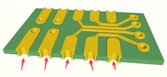
This video explains castellated holes (also known as castellations or half-holes) - semi-circular plated pads along the edge of a PCB that allow one board to be soldered directly onto another, creating strong, space-saving module connections.
The manufacturing process starts with standard plated through-holes. After copper plating the barrel, the board edge is precisely milled to expose the characteristic half-moon shape. This technique is widely used in Wi-Fi, Bluetooth, and compact expansion modules where quick, reliable vertical or horizontal board stacking is needed.
Key design considerations include finished hole diameter (recommended ≥0.5 mm), pad spacing (≥0.5 mm), and exact centering on the cut line. Misalignment or poor plating can lead to weak joints, especially under thermal stress or mechanical vibration.
Properly designed castellated holes improve assembly efficiency and reliability in IoT devices, industrial control systems, and consumer electronics.
Request an instant PCB quote for your castellated board project. For full turnkey production, explore our PCB assembly services. Prototype your next modular design with confidence through our PCB prototyping service.
KEY HIGHLIGHTS
- Castellated holes are created by drilling and plating through-holes, then milling the board edge to form half-moon pads for direct board-to-board soldering.
- Minimum recommended specifications: finished hole diameter ≥0.5 mm and pad spacing ≥0.5 mm with precise alignment on the cut line.
- Ideal for Wi-Fi, Bluetooth, and modular IoT designs, but require tight fabrication tolerances to ensure strong, reliable solder joints under thermal and mechanical stress.
Step-by-Step Manufacturing Process Behind Castellated Holes
Castellated holes, also referred to as plated half-holes, start as standard through-holes drilled in the production panel. These holes undergo electroless and electrolytic copper plating to create a continuous conductive barrel with adequate thickness for both electrical performance and mechanical durability during subsequent processing. After completing outer layer patterning, solder mask application, and surface finishing, the panels proceed to depanelization.
Precision CNC routing then bisects the plated holes exactly at their centers, revealing the characteristic semi-circular pads. This milling operation uses specialized heavy-duty router bits capable of handling the harder copper without excessive wear or creating burrs that could affect solderability. Post-milling cleaning and deburring steps remove any debris, ensuring clean, reliable solderable edges.
Panelization layout plays a significant role in yield. Castellated features require careful placement relative to break tabs and panel borders to prevent damage or distortion. In multilayer boards, registration accuracy across all layers is vital to maintain consistent half-hole geometry. Fabricators often apply additional process controls for castellated orders to meet tight tolerances demanded by module applications.
Essential DFM Guidelines and Tolerances for Flawless Castellated Designs
Reliable castellated hole production depends on strict design parameters. The finished hole diameter should be at least 0.5 mm, with 0.6–0.8 mm preferred for most fabricators to ensure uniform plating and easier milling. Minimum edge-to-edge spacing of 0.5–0.55 mm helps prevent solder bridging during assembly, while annular rings of 0.15 mm minimum (ideally 0.25 mm) anchor the copper securely to the laminate.
| Parameter | Minimum Value | Recommended Value | Practical Impact |
|---|---|---|---|
| Finished Hole Diameter | 0.5 mm | 0.6–0.8 mm | Plating uniformity and milling quality |
| Edge-to-Edge Spacing | 0.5 mm | ≥0.55 mm | Solder bridging prevention |
| Annular Ring Width | 0.15 mm | 0.25 mm+ | Resistance to delamination |
| Inward Pad Extension | 0.25 mm | 0.5 mm+ | Mechanical strength of joint |
| Outline Alignment | Hole center | Precise center | Clean half-hole formation |
Designers should define holes as plated through-holes in CAD, place the board outline through the exact center, and include top/bottom pads with open solder mask. ENIG surface finish is typically superior for these features due to its flatness and oxidation resistance. Early manufacturer consultation helps resolve potential EQs on tight designs.
Real-World Applications and Benefits in Modular Electronics
Castellated holes provide an efficient solution for mounting compact modules such as Wi-Fi, Bluetooth, and sensor boards directly onto main PCBs. They reduce overall product height and eliminate the need for additional connector components, lowering BOM cost and simplifying automated assembly processes in high-volume IoT and consumer electronics production.
Critical Failure Modes in Castellated Hole Production and How to Prevent Them
Common issues observed in manufacturing include copper delamination during milling caused by insufficient annular rings, asymmetric half-holes from registration errors, weak solder joints due to poor plating or misalignment, and bridging from inadequate spacing. These problems become more pronounced under thermal cycling or vibration, potentially leading to field failures in deployed devices.
Prevention starts with conservative DFM parameters, thorough prototype validation including cross-sectional analysis, and selection of appropriate surface finishes. Specifying castellated requirements clearly in fabrication notes and working with experienced manufacturers ensures process controls are applied. Post-assembly inspection and reliability testing further confirm joint integrity before scaling to production.
FAQ
Q1: What are the minimum design rules for castellated holes?
A1: Maintain finished hole diameter of at least 0.5 mm, pad spacing of 0.5 mm or more, and ensure the hole is perfectly centered on the board edge cut line for strong solder joints.
Q2: How are castellated holes manufactured on PCBs?
A2: The process involves drilling plated through-holes, copper plating the barrels, then precision milling the board edge to create the half-hole castellations.
Q3: When should you use castellated holes instead of connectors?
A3: Use castellated holes for compact, low-profile module connections (such as Wi-Fi or sensor boards) where space is limited and direct soldering provides better reliability and lower cost than traditional connectors.
Q4: What surface finish is best for castellated holes and why?
A4: ENIG is preferred as it delivers excellent solder wettability on the exposed edges, remains flat, and resists oxidation better than alternatives, leading to more consistent assembly results.
Q5: How can designers prevent delamination in castellated hole areas?
A5: Provide adequate annular rings (≥0.25 mm recommended), extend pads sufficiently inward, consider inner layer pads on multilayer boards, and maintain proper milling tolerances. Prototype validation with cross-section inspection is highly recommended.
Ever noticed tiny half-circles along a PCB's edge, like neat castle battlements?
Those are castellated holes — they let one board solder directly to another, almost snapping two modules together.
You'll often find them on Wi-Fi, Bluetooth, or compact expansion boards where quick edge-to-board connections matter.
The process seems easy, but accuracy is key. First, a plated through-hole is made, then copper coats the barrel, finally the edge is milled to turn the via into a half-moon pad. Misalignment or uneven plating weakens joints, especially after repeated heating or stress.
For stronger soldering,keep finished hole diameter≥0.5 mm,adjacent pad spacing ≥0.5 mm and center the hole exactly on the cut-line.
Small tweaks make half-hole boards better — what tips worked best for you?
This is aivon, making PCB learning easier,comment below — and follow for more PCB tips!





