Why Is Thoughtful PCB Design Crucial for Pet Trackers?
Pet tracking devices have become indispensable for owners monitoring their animals. These compact gadgets depend entirely on a well-engineered Printed Circuit Board (PCB) to integrate essential features like GPS, various communication modules, and power systems into a small, wearable form factor. The quality of the PCB design directly influences the device's effectiveness and reliability.
A subpar PCB can lead to several problems, including signal loss, excessive power consumption, or even complete device failure—any of which could result in losing track of a pet. Emphasizing a robust PCB layout, meticulously chosen components, and an optimized design ensures that the pet tracker performs reliably and consistently.

How Do You Plan an Effective Pet Tracking PCB Layout?
The starting point for any successful pet tracking device is a thoroughly planned PCB layout. This layout dictates the placement and interconnections of all components, which in turn affects signal integrity, power efficiency, and the device's overall physical size. Given that pet trackers must be lightweight and small enough to attach to a collar, maximizing space is a primary concern.
Begin by identifying the core functions your device needs. Most pet trackers include GPS for location, a wireless communication system (such as cellular or Bluetooth), a microcontroller for data processing, and a power source. Position these components using your PCB design software, making sure to minimize interference, especially between high-frequency signals like GPS and other circuitry.
Layout Strategies for Optimal Performance
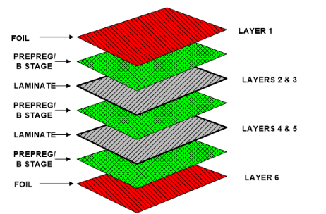
To maintain signal integrity, keep high-speed signal traces as short and direct as possible. For instance, GPS signals operate around 1.575 GHz, so shorter traces prevent signal degradation. Sensitive parts, like the GPS module, should be kept away from noisy elements such as power regulators. Employing a multilayer PCB—typically four layers—is also advisable to separate power, ground, and signal planes, enhancing noise isolation.
Which Components Are Essential for a Pet Tracking PCB?
Selecting the right components is vital for the functionality and compact size of a pet tracking device. Here’s a detailed look at the necessary parts and tips for choosing them wisely:
Key Component Selection Guidelines
● GPS Module: Choose a compact, low-power GPS module. Aim for sensitivity of at least -160 dBm to ensure accurate tracking even in areas with weak signals.
● Microcontroller (MCU): Opt for a low-power MCU with sufficient processing power for GPS data and communication protocols. A 32-bit MCU operating at 48 MHz or higher is typically adequate.
● Communication Module: Your choice depends on the required range. Cellular modules (e.g., 4G LTE Cat-M1) offer broad coverage with low power usage for long-range tracking, while Bluetooth is suitable for shorter distances.
● Battery and Power Management: A small, rechargeable lithium-ion battery (around 3.7V, 500mAh) paired with a Power Management IC (PMIC) is recommended for stable voltage regulation and extended battery life.
● Optional Sensors: Incorporating accelerometers can detect pet movement, allowing the device to enter sleep mode when stationary and conserve power.
When sourcing, prioritize components in small packages like QFN or BGA to save PCB space. Always review datasheets for power and thermal characteristics to prevent overheating, particularly in a small collar-mounted device.
How Do You Design the Antenna for a Pet Tracking PCB?
The antenna is central to wireless communication in any pet tracking device, making its design a crucial step. An improperly designed antenna can severely limit the tracker's range and reliability due to weak signals. Since pet trackers often utilize GPS, cellular, or Bluetooth, you might need multiple antennas or a single multi-band antenna.
For GPS, a ceramic patch antenna is a popular choice because of its small size and typically 2-5 dBi gain. Position this antenna on the PCB’s top layer, ensuring a clear ground plane beneath it to enhance signal reception. Always maintain a specified keep-out area—often 5mm—around the antenna to prevent interference from other components.
For cellular or Bluetooth communication, consider a PCB trace antenna or a chip antenna. Trace antennas are economical and can be integrated directly onto the PCB, but they require precise 50-ohm impedance matching for maximum efficiency. Fine-tuning antenna performance during testing with a network analyzer is recommended.
Antenna placement is also critical; it should be away from any metallic collar or enclosure parts, as metal can detune the antenna and degrade performance. If space is tight, consider embedding the antenna within the PCB layout, but be prepared for design iterations to achieve optimal results.
What Are the Best Practices for Pet Tracking PCB Power Optimization?
Power efficiency is paramount for pet tracking devices, which typically rely on small batteries and need to operate for days or weeks between charges. Effective PCB power optimization can dramatically extend battery life and ensure long-term reliability.
Begin by selecting components with inherently low power consumption. For example, choose a GPS module that supports duty-cycling, activating only periodically to update location data. Similarly, use an MCU with deep sleep modes that draw less than 10 μA when idle.
Design your power management circuit to minimize energy loss. A buck-boost converter can ensure a stable output voltage (e.g., 3.3V) for components, especially if the battery voltage fluctuates significantly during discharge. Adding bypass capacitors, typically 0.1 μF ceramic capacitors, near IC power pins helps reduce high-frequency noise.
Software also plays a significant role in power optimization. Program the device to enter sleep mode when the pet is inactive, using an accelerometer to trigger wake-ups only during movement. This strategy can reduce power consumption by up to 80% in certain scenarios.
Finally, rigorously test the power draw of your assembled PCB using a multimeter to identify any unexpected current leaks. A well-optimized pet tracker should aim for an average current draw below 5 mA in active mode and under 100 μA in sleep mode.

Key Considerations for Designing a Pet Tracking PCB Enclosure?
The enclosure for a pet tracking PCB serves to protect the sensitive electronics from moisture, dust, and physical impacts, while also ensuring the device remains comfortable for the pet. A well-designed enclosure also influences signal performance and battery accessibility.
Select a lightweight, durable material such as ABS plastic, which offers good impact resistance and can be easily molded into small forms. The enclosure should have an IP65 rating or higher for water and dust resistance, accounting for pets' outdoor activities.
Size is a critical factor; the enclosure must be compact enough to fit on a collar without causing discomfort—dimensions around 40mm x 30mm x 10mm are often suitable for small to medium pets. Ensure adequate internal space for the fast turn PCB, battery, and antenna to prevent overcrowding and potential heat buildup.
Pay close attention to antenna placement within the enclosure. Avoid covering the antenna area with metal or thick plastic, as these can block signals. If possible, design a thin window or use a less dense material over the antenna to maintain signal strength.
Finally, consider the mechanism for attaching the enclosure to the collar. A secure clip or loop works well, and some designs may include a slot for easy battery replacement or charging access. Prototype testing of the enclosure is essential to confirm its durability against daily wear and tear from an active pet.