Introduction
Aerodynamic design remains one of the most challenging aspects of aircraft and launch vehicle development. From conceptual layout to final validation, engineers must balance performance, stability, structural integrity, and cost. Computational Fluid Dynamics (CFD) has transformed this process by enabling early high-fidelity analysis, while wind tunnel testing continues to provide essential validation. For avionics and PCB manufacturers, aerodynamic decisions directly influence vibration profiles, thermal loads, sensor placement, and the reliability requirements of onboard electronics.
Evolution of Aerodynamic Layout Design Processes
Traditional aircraft design relied heavily on engineering experience to generate multiple configurations within practical constraints, followed by parametric modeling and wind tunnel validation. Modern workflows integrate high-fidelity 3D models and CFD simulations much earlier in the cycle. This shift allows engineers to evaluate performance, identify issues, and optimize designs cost-effectively before committing to physical prototypes - particularly valuable for complex shapes where early risk reduction is critical.
Case Studies in Aerodynamic Design
Su-27 Fighter: Iterative Innovation
The Su-27 program exemplifies persistent iteration. The initial T-10 prototype revealed significant shortcomings, leading to a comprehensive redesign. The improved T-10S variant first flew in 1981 after extensive prototyping and testing. This approach - rapid layout optimization combined with multiple flight tests - demonstrates how embracing new technologies and iterative refinement can overcome initial challenges, a philosophy echoed in modern programs like SpaceX.
Recoverable Rocket Stages and Grid Fins
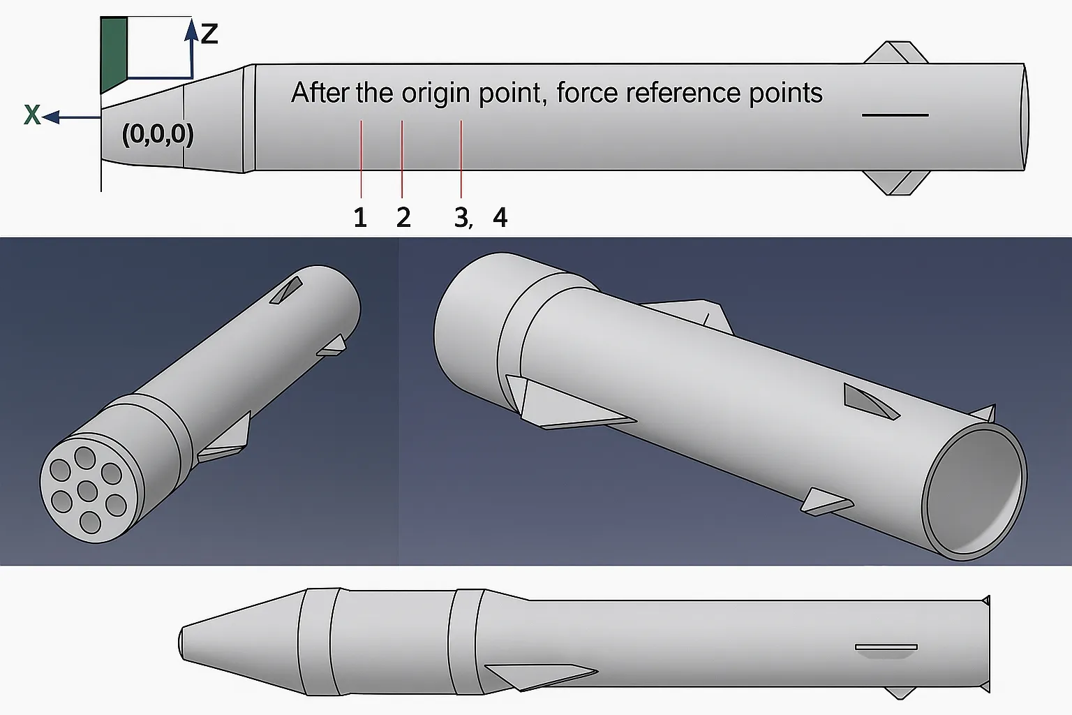
Stage recovery for heavy launch vehicles introduces unique aerodynamic challenges, including center-of-mass shifts and trim angles at supersonic speeds. Analyses of concepts similar to "New Glenn" highlight how boattail designs affect drag and stability. Grid fins, used for control during re-entry, require careful geometric optimization. Rounding windward edges can reduce heat flux by up to 50%, while different honeycomb configurations (framed, upright, tilted) influence structural and aerodynamic performance.
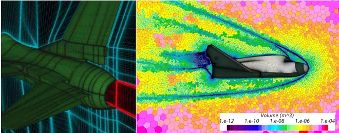
Design Methods: Combining Testing and CFD Simulation
Effective aerodynamic development requires both physical testing and numerical simulation:
Role of Wind Tunnel Testing
Ground-based high- and low-speed wind tunnels remain foundational for complex configurations. They provide reliable data for high-lift conditions (takeoff/landing), stall behavior, unsteady flows, and component interactions where CFD still has limitations.
Strengths and Limitations of CFD
CFD serves as a powerful "numerical wind tunnel," enabling rapid parametric studies, multidisciplinary optimization, and simulation of conditions difficult to replicate physically. However, it can underpredict certain phenomena (e.g., maximum lift at high angles of attack) and demands significant computational resources for unsteady simulations using LES or DES.
The optimal strategy combines early CFD for concept exploration with targeted wind tunnel validation for critical performance metrics.
Design Tools: Meshing and Solvers
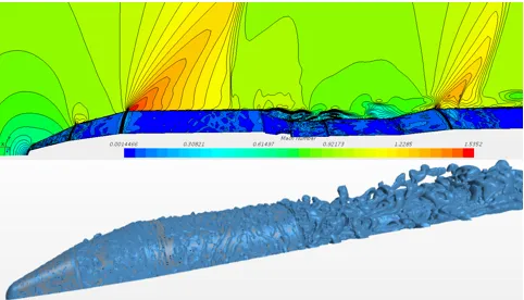
Mesh Quality
Mesh generation is often the most influential factor in CFD accuracy. Structured meshes offer superior resolution of near-wall viscous effects and are preferred for aerodynamic heating studies, while unstructured meshes provide flexibility for complex geometries. Proper node distribution and boundary layer resolution (appropriate Y+ values) are essential regardless of mesh type.
Solver Selection
Choosing the right turbulence model and solver depends on the specific flow regime. Engineering judgment is critical - tools must match the physics of the problem rather than relying on default settings.
User vs. Tool Responsibility
Discrepancies between simulation and test results often stem from inappropriate tool selection or improper application (mesh settings, boundary conditions, or model calibration) rather than fundamental software limitations.
PCB Design and Electronics Manufacturing Considerations in Aerodynamic Contexts
Aerodynamic design choices have direct downstream effects on aerospace electronics:
- Vibration and Mechanical Loads: High-performance layouts with grid fins, control surfaces, or re-entry profiles generate complex vibration environments. PCBs must incorporate reinforced mounting, rigid-flex constructions, and vibration-dampening strategies.
- Thermal Management: Aerodynamic heating during supersonic flight or re-entry demands advanced thermal vias, high-Tg laminates, and efficient heat dissipation paths on avionics boards.
- Sensor and Avionics Integration: Accurate CFD data informs optimal placement of IMUs, air data sensors, and antennas. High-speed signal integrity for flight control and telemetry systems requires careful impedance control and shielding.
- Reliability Engineering: Aerospace-grade PCBs for these platforms need conformal coatings, redundant designs, and rigorous environmental testing to withstand the combined effects of vibration, thermal cycling, and electromagnetic environments influenced by aerodynamic features.
- Miniaturization and Power Efficiency: Lightweight airframes and optimized aerodynamics push for compact, high-density interconnect (HDI) electronics with efficient power distribution.
Industry Trends
The synergy between CFD, wind tunnel testing, and iterative prototyping continues to accelerate development cycles. Future aircraft and reusable launch vehicles will demand even tighter integration between aerodynamic optimization and electronics systems, including AI-assisted design and real-time digital twins.
Supporting Aerodynamic Technologies Through Aerospace Electronics Manufacturing
Advanced aerodynamic design and CFD analysis set stringent requirements for the electronic systems that control and monitor aircraft performance. High-reliability PCB fabrication, rigid-flex solutions, thermal optimization, and vibration-resistant assembly are essential to translate aerodynamic excellence into safe, efficient, and mission-capable aerospace platforms.
FAQs
Q1: Why is CFD important in modern aircraft design?
A1: CFD enables early performance prediction, parametric optimization, and simulation of complex flows, significantly reducing development time and cost when combined with wind tunnel validation.
Q2: What are the limitations of CFD compared to wind tunnel testing?
A2: CFD may underpredict high-lift or stall characteristics and requires substantial resources for accurate unsteady flow simulation. Physical testing remains essential for validation of critical phenomena.
Q3: How do aerodynamic designs affect avionics and PCB requirements?
A3: They influence vibration profiles, thermal loads, sensor placement, and overall system reliability, requiring ruggedized, high-performance PCBs with excellent mechanical and thermal characteristics.