Introduction
Unlike traditional pedometers, a belt-type pedometer is embedded within a belt, reducing wearable bulk and eliminating the need for a second wearable. Using the low-power, high-precision ADXL345 sensor enables accurate step counting. Experiments show the belt pedometer is compact, simple in structure, stable, and meets step-counting requirements.
As wearable devices become more common, pedometers help users record walking steps and quantify exercise. Compared with wrist-worn or pocket devices, a waist-mounted pedometer is easier to implement accurately and at lower cost, although it requires being worn at the waist.
1 Hardware Design
1.1 ADXL345 sensor
The pedometer consists of an ADXL345 accelerometer, an STC90C51 microcontroller, an LCD1602 display, a reset button, and a power source. The ADXL345 is a small, thin, ultra-low-power 3-axis accelerometer with a measurement range up to ±16 g. Its high resolution (3.9 mg/LSB) can detect tilt changes below 1.0°. The sensor works by sensing acceleration in three axes, converting the sensed physical quantities into analog signals, then using an A/D converter to produce digital signals. After digital filtering, data are sent to control and interrupt logic and exchanged with the host via a serial I/O interface under command control.
1.2 I2C bus communication
The ADXL345 supports SPI and I2C interfaces with a host processor. This design uses the I2C bus. The I2C bus uses SDA (data) and SCL (clock) lines to send and receive data. It supports bidirectional transfers between a CPU and peripheral ICs or between ICs, with a typical maximum transfer rate of 100 kbps. Main advantages of I2C include a small pin and board footprint and support for multiple masters. If the CS pin is pulled high to VDD I/O, the I2C interface is enabled. The ADXL345 has a configurable I2C address of 0x53, which can be selected by the SDO pin; in that case write operations use 0xA6 and read operations use 0xA7. Typical operation: issue a START condition, send the register address to the slave (ADXL345), read six consecutive data bytes into a receive buffer, the slave acknowledges each byte, and finally send a STOP condition to end the transfer.
1.3 STC90C51 microcontroller
The STC90C51 is an enhanced 8051-class microcontroller featuring strong interference immunity, high speed, and low power. It integrates a CPU, program memory (Flash), data memory (RAM), timers/counters, UART, I/O ports, EEPROM, and a watchdog on a single chip. Operating voltage is 3.3 V to 5.5 V with 40 pins and 35 general-purpose I/O. In this design, the microcontroller reads data from the ADXL345, processes and interprets the sensor data, and drives the LCD1602 to present commands and step counts. The system also includes a reset button and a power switch.
1.4 LCD1602 display
The LCD1602 character LCD is used as the system display. It displays letters, numbers, and symbols using 5x7 or 5x11 dot-matrix characters. Pins 1 and 2 are the power supply; pin 3 adjusts contrast; pin 4 selects data/command and connects to the microcontroller port P1.0; pin 5 selects read/write and connects to P1.1; pin 6 is Enable and connects to P2.5; pins 7 to 14 are the 8 data I/O lines; pins 15 and 16 power the backlight. Initialize the LCD1602 by configuring cursor and display settings, write commands to set the display position, and then write characters to show on the screen.
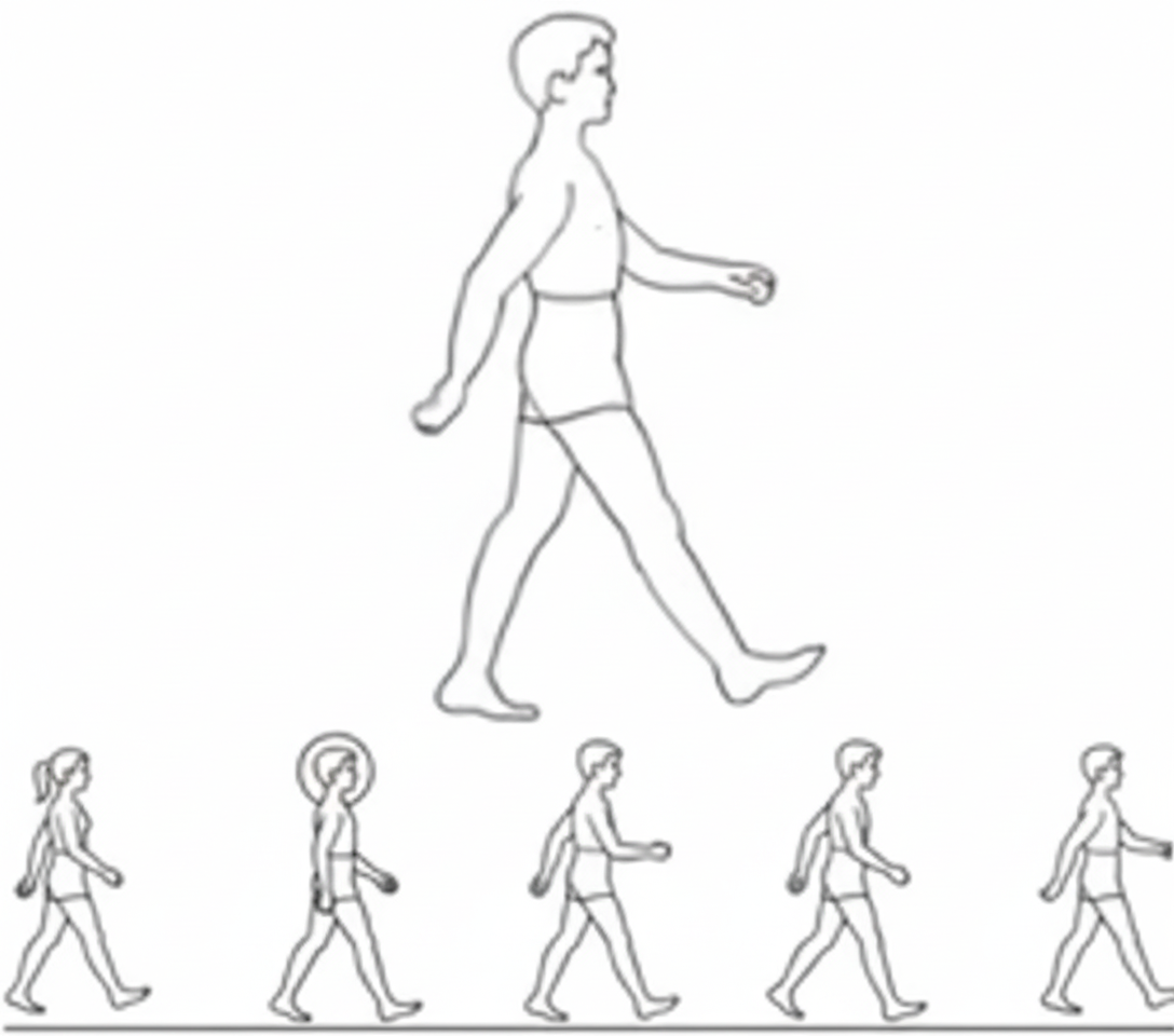
2 Human Walking Model
Human walking produces changes in parameters such as distance, energy, and acceleration. Describing walking by acceleration changes is a simple and feasible method. Detecting steps from foot acceleration is most accurate, but for convenience this design uses waist motion to detect steps. Waist acceleration can be decomposed into vertical, forward, and lateral axes. The ADXL345 provides three-axis outputs (X, Y, Z), which correspond to vertical, lateral, and forward directions for this application. The vertical (X) and forward (Z) axes show distinct periodic characteristics. The vertical acceleration minimum corresponds to the foot leaving the ground (the start or end of a step) and the maximum corresponds to the foot at its highest point. The forward-axis acceleration follows a similar pattern, with minima at foot lift-off and maxima at the highest foot position.