Overview
Digital load scales are common tools in engineering and product design. This project explains how a typical weight scale works and shows how to build a portable load scale using an HX711 ADC and an Arduino that can measure up to 10 kg.
Use Case
The scale design presented here is suitable for small shops that need to package items by weight. The scale includes a tare (zero) function and the ability to set a target weight. When the measured weight approaches the target, a buzzer emits faster beeps, allowing operators to pack items by sound rather than watching the display.
Key Components
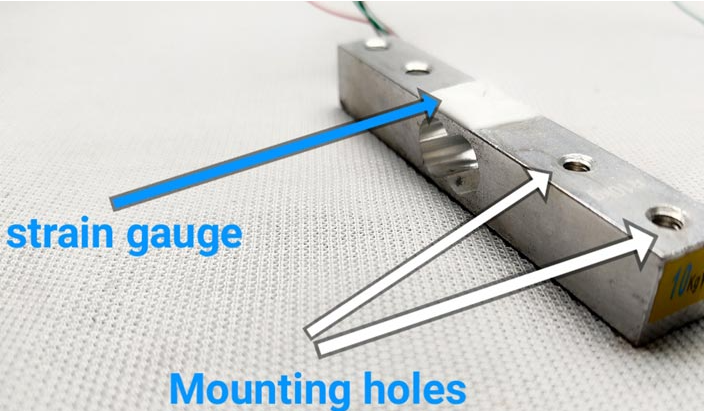
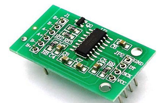
The primary components are the load cell and the HX711 amplifier module. The load cell used here is rated for 10 kg. You will notice a white protective coating on the load cell; beneath it are the strain gauges and four wires. The wiring colors may vary by manufacturer, so always check the datasheet.
How the Load Cell Works
A load cell converts applied force or pressure to an electrical signal. The typical single-point load cell is machined from an aluminum block with a reduced cross-section where deflection occurs when the load is applied. One side is fixed to the base and the other side receives the load. When the load side is loaded, the top experiences tension and the bottom compression, causing the metal to bend. Measuring that deformation allows us to infer the applied force.
Under the white coating are very thin elastic elements called strain gauges. A strain gauge is a component used to measure strain. It has solder pads and a patterned conductive trace with a defined resistance. Bending the gauge changes that resistance: tension increases the resistance and compression reduces it. The change in resistance is typically very small, so it is converted into a small voltage change by arranging the strain gauges in a Wheatstone bridge.
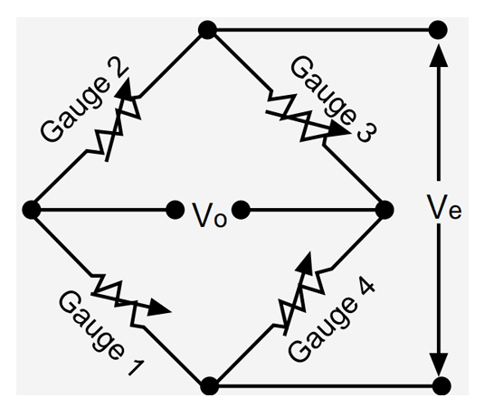
The Wheatstone bridge converts the small resistance changes into a differential voltage at the bridge output. Because the resulting voltage is still very small, the HX711 module is used. The HX711 is a 24-bit differential ADC designed for load cell applications, enabling measurement of very small voltage variations.
Required Parts
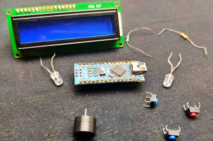
To keep the project simple, the parts used are common and readily available. The main parts include:
- 10 kg load cell
- HX711 amplifier module
- Arduino Nano
- I2C 16x2 LCD
- 1 kΩ resistors, 2 pcs
- LEDs, 2 pcs
- Buzzer
- Generic perfboard
- 7.4 V battery (for portability)
- LM7805 voltage regulator
Wiring and Circuit
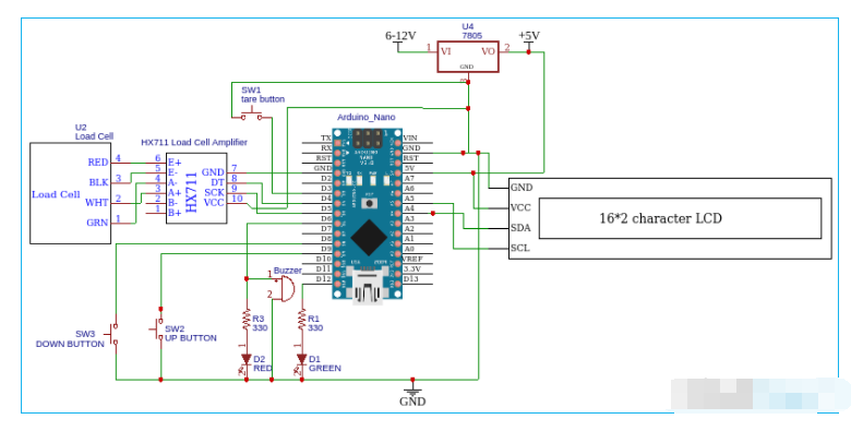
The load cell has four wires, typically red, black, green, and white, though colors vary by vendor. In this build the connections are:
- Red to E+
- Black to E-
- White to A+
- Green to A-
The HX711 data output (Dout) and clock pins connect to two Arduino pins (D4 and D5 in the example). Buttons connect to D3, D8, and D9, with their other side tied to ground. For the I2C LCD, SDA goes to A4 and SCL goes to A5. Connect grounds of LCD, HX711, and Arduino together, and VCC to the Arduino 5V pin. All modules operate at 5V; the LM7805 regulator is used when powering from a battery. If the unit is not portable, you can power the Arduino directly from USB.
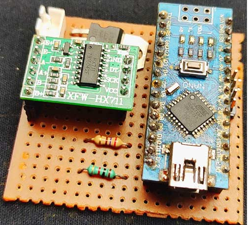
Prototyping on Perfboard
All components were soldered onto a standard perfboard. Female headers were used for the Arduino and ADC so the modules can be removed. Buttons and LEDs were wired with insulated wire. After soldering, verify the LM7805 output is a steady 5V, then add a power switch to enable/disable the circuit.
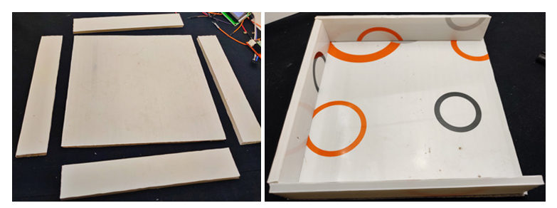
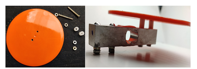
Enclosure and Mechanical Assembly
The load cell includes threaded mounting holes so it can be attached to a base. For the base, PVC sheets were cut into a 20 x 20 cm square plus four 20 x 5 cm strips to form a small enclosure. One side of the enclosure remains removable to mount the buttons, LEDs, and LCD. A top plastic plate serves as the weighing surface. Ensure there is enough clearance between the load cell and the base so the load cell can deflect; spacers and nuts are placed between the load cell and the top plate to allow movement. A round plastic plate was used on top to distribute load.
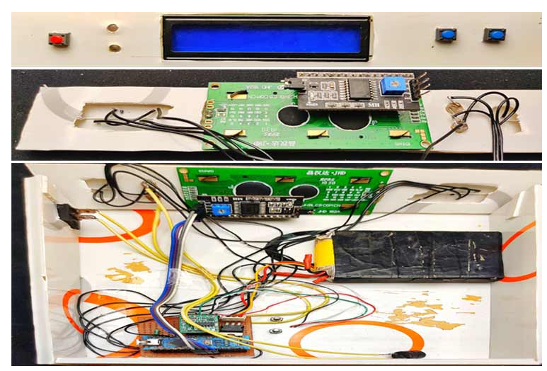
The LCD, LEDs, and buttons were mounted in the front panel and wired with insulated wires. The front panel was angled for easier reading of the LCD, and the main power switch was added to one side.
Software and Calibration
The software uses the HX711 library, the EEPROM library, and the LiquidCrystal I2C library. Install the HX711 library from its official repository or via the Arduino IDE Library Manager using the keyword HX711.
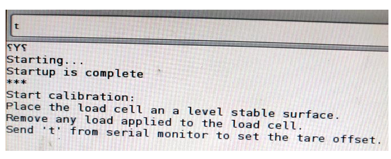
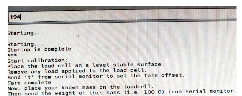
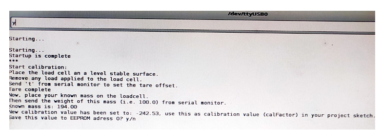
First calibrate the load cell and store the calibration factor in EEPROM. Use the HX711_ADC examples in the Arduino IDE and select the calibration sketch. With the scale on a stable surface, upload the calibration sketch to the Arduino and open the serial monitor at 57600 baud. Follow the prompts to tare and place a known weight on the scale, then enter the known weight. When prompted, save the calibration factor to EEPROM.
Key Program Details
The main code is derived from the HX711 library example sketch. The HX711 library reads raw data from the load cell. EEPROM is used to store and retrieve the calibration factor. LiquidCrystal_I2C drives the I2C LCD. Below are the code blocks from the article; only comments inside the code have been translated to English. All code symbols, indentation, and variable names have been preserved exactly as in the original examples.
#include <hx711_adc.h> #include <eeprom.h> #include <liquidcrystal_i2c.h>
常量 int HX711_dout = 4; 常量 int HX711_sck = 5; 诠释 tpin = 3; HX711_ADC LoadCell(HX711_dout, HX711_sck); 常量 int calVal_eepromAdress = 0; 长 t; 常量 int Up_buttonPin = 9; 常量 int Down_buttonPin = 8; 浮动按钮PushCounter = 0; 浮动 up_buttonState = 0; 浮动 up_lastButtonState = 0; 浮动 down_buttonState = 0; 浮动 down_lastButtonState = 0;
pinMode(tpin,INPUT_PULLUP); pinMode(6,输出); pinMode(12,输出); pinMode(Up_buttonPin,INPUT_PULLUP); pinMode( Down_buttonPin , INPUT_PULLUP);
液晶显示器(); 液晶背光(); lcd.setCu$rsor(0, 0); lcd.print("ARDUINO 平衡"); lcd.setCursor(0, 1); lcd.print("让我们测量一下"); 延迟(2000); lcd.clear();
LoadCell.begin(); EEPROM.get(calVal_eepromAdress,calibrationValue);
if (LoadCell.update()) newDataReady = true; if (newDataReady) { if (millis() > t + serialPrintInterval) { float i = LoadCell.getData(); lcd.setCursor(0, 0); lcd.print("设置 wei:"); lcd.setCursor(9, 0); lcd.print(buttonPushCounter); lcd.setCursor(14, 0); lcd.print("GM"); lcd.setCursor(0, 1); lcd.print("重量:"); lcd.setCursor(9, 1); lcd.print(i); lcd.setCursor(14, 1); lcd.print("GM");
if (digitalRead(tpin) == LOW) { LoadCell.tareNoDelay();
浮动 k = buttonPushCounter-i ;
if ( k >= 50 ) { digitalWrite (6, HIGH); 延迟(200); 数字写入(6,低); 延迟(200); }
if ( k < 50 && k > 1 ) { digitalWrite (6, HIGH); 延迟(50); 数字写入(6,低); 延迟(50); }
if(i>=buttonPushCounter) { digitalWrite (6, LOW); 数字写入(12,高); }
Calibration and Button Handling Functions
Two helper functions handle the up and down buttons to adjust the target weight. Each press changes the target by 10 g using digitalRead to detect button presses.
up_buttonState = digitalRead(Up_buttonPin); if (up_buttonState != up_lastButtonState) { if (up_buttonState == LOW) { bPress = true; buttonPushCounter = buttonPushCounter + 10; }
down_buttonState = digitalRead(Down_buttonPin); if (down_buttonState != down_lastButtonState) { if (down_buttonState == LOW) { bPress = true; buttonPushCounter = buttonPushCounter - 10; }
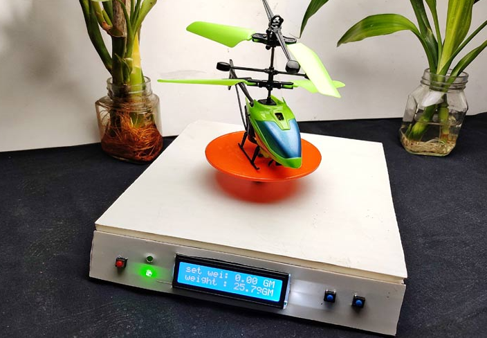
Results
The assembled Arduino-based scale measures weights up to 10 kg with an accuracy close to ±1% against the original measured values. Using a load cell with a higher rating would raise the maximum measurable weight.
Full Example Code (excerpt)
The following excerpt includes the main setup and loop structure used in the example. Comments translated to English are provided inline. Preserve the libraries and calibration steps described earlier when running the full sketch.
#include <hx711_adc.h> #include <eeprom.h> #include <liquidcrystal_i2c.h> LiquidCrystal_I2C lcd(0x27, 2, 16); HX711_ADC LoadCell(HX711_dout, HX711_sck); 常量 int HX711_dout = 4; // MCU > HX711 output pin 常量 int HX711_sck = 5; // MCU > HX711 sck pin 诠释 tpin = 3; 常量 int calVal_eepromAdress = 0; 长 t; 常量 int Up_buttonPin = 9; // Pin connected to the up button 常量 int Down_buttonPin = 8; 浮动按钮PushCounter = 0; // Counter for button presses 浮动 up_buttonState = 0; // Current state of up button 浮动 up_lastButtonState = 0; // Previous state of up button 浮动 down_buttonState = 0; // Current state of down button 浮动 down_lastButtonState = 0; // Previous state of down button 布尔 bPress = 假; 无效设置(){ 序列号.开始(57600); 延迟(10); 序列号.println(); Serial.println("开始..."); pinMode(tpin,INPUT_PULLUP); pinMode(6,输出); pinMode(12,输出); pinMode(Up_buttonPin,INPUT_PULLUP); pinMode( Down_buttonPin , INPUT_PULLUP); 液晶显示器(); 液晶背光(); lcd.setCursor(0, 0); lcd.print("ARDUINO 平衡"); lcd.setCursor(0, 1); lcd.print("让我们测量一下"); 延迟(2000); lcd.clear(); LoadCell.begin(); 浮动校准值;// Calibration value (see example file "Calibration.ino") 校准值 = 696.0;// If setting calibration value in sketch, uncomment #如果定义(ESP8266)|| 定义(ESP32) //EEPROM.begin(512); // If using ESP8266/ESP32 and want to read calibration from EEPROM, uncomment #万一 EEPROM.get(calVal_eepromAdress,calibrationValue); // If reading calibration from EEPROM, uncomment 稳定时间长 = 2000;// Increasing this gives better accuracy after power-up 布尔_皮重=真;// If you do not want to perform a tare on startup, set to false LoadCell.start(稳定时间,_皮重); if (LoadCell.getTareTimeou&tF;lag()) { Serial.println("Timeout, check MCU>HX711 wiring and pin names"); 而(1); } 别的 { LoadCell.setCalFactor(校准值);// Set calibration value (float) Serial.println("启动完成"); } } 无效循环(){ 静态布尔 newDataReady = 0; 常量 int serialPrintInterval = 0; // Increase to slow serial print activity // Check for new data / start next conversion: if (LoadCell.update()) newDataReady = true; // Get smoothed value from dataset: 如果(新数据就绪) { if (millis() > t + serialPrintInterval) { 浮动 i = LoadCell.getData(); Serial.print("Load_cell 输出值:"); 序列号.println(i); 新数据就绪 = 0; t = 毫秒(); lcd.setCursor(0, 0); lcd.print("设置 wei:"); lcd.setCursor(9, 0); lcd.print(buttonPushCounter); lcd.setCursor(14, 0); lcd.print("GM"); lcd.setCursor(0, 1); lcd.print("重量:"); lcd.setCursor(9, 1); lcd.print(i); lcd.setCursor(14, 1); lcd.print("GM"); } } 清理( ); checkDown(); 如果(数字读取(tpin)==低){ LoadCell.tareNoDelay(); } // Check whether the last tare operation has completed: if (LoadCell.getTareStatus() == true) { lcd.clear(); lcd.print("去皮完成"); 延迟(1000); lcd.clear(); } 浮动 i = LoadCell.getData(); 浮动 k = buttonPushCounter - i; 如果 ( k < 50 && k > 1 ) { 数字写入(6,高); 延迟(50); 数字写入(6,低); 延迟(50); } 如果 ( k >= 50 ) { 数字写入(6,高); 延迟(200); 数字写入(6,低); 延迟(200); } if (i >= buttonPushCounter) { 数字写入(6,低); 数字写入(12,高); } 别的 { 数字写入(12,低); } } 无效检查() { up_buttonState = digitalRead(Up_buttonPin); // Compare buttonState to previous state if (up_buttonState != up_lastButtonState) { // If the state has changed, increment the counter 如果(up_buttonState == LOW) { bPress =真; // If the current state is HIGH, the button changed from off to on: buttonPushCounter = buttonPushCounter + 10; } } // Save the current state as the last state for next loop up_lastButtonState = up_buttonState; } 无效 checkDown() { down_buttonState = digitalRead(Down_buttonPin); // Compare buttonState to previous state if (down_buttonState != down_lastButtonState) { // If the state has changed, increment the counter 如果(down_buttonState == LOW) { bPress =真; buttonPushCounter = buttonPushCounter - 10; } } // Save the current state as the last state for next loop down_lastButtonState = down_buttonState; }
Note: The example sketches and libraries referenced include the calibration routine and EEPROM handling needed to store the calibration factor. Follow the HX711 library documentation and example sketches to complete the setup and calibration steps before relying on the scale for measurements.