Overview
The BYD Seal is built on the new pure-electric e-platform 3.0, which integrates the battery into the vehicle body and continues the blade battery architecture. The e-platform 3.0 also introduces an eight-in-one electric powertrain assembly, covering the drive assembly (motor and gearbox), motor controller, PDU (power distribution unit), DC-DC, OBC, VCU, and BMS. BYD offers Seal versions with approximately 600 km and 700 km range, which compare favorably with Model 3 variants rated at 556 km and 675 km.
Stator Design
The motor is a flat-wire, hairpin, multi-phase AC, oil-cooled, rotor permanent-magnet synchronous motor. To evaluate its performance, focus on two main loss sources: copper loss and iron loss. Optimizing these requires attention to both stator and rotor design.
Why a Rotor Permanent-Magnet Design?
Permanent magnets are rarely placed on the stator because integrating windings into the rotor is mechanically and electrically challenging. Rotating windings require complex current collection methods such as slip rings to supply large three-phase currents, which increases cost and reliability concerns, especially at high speed and torque. For these practical reasons, automotive motors typically use permanent magnets on the rotor.
What Is Flat Wire?
Flat wire replaces round copper wire with rectangular cross-section copper bars. Since high-power motor windings heat under heavy current and copper loss follows an I2R relation, reducing resistance within the same package limits heat generation. Rectangular cross-sections increase effective conductor radius relative to enclosed area, lowering resistance and heat.
Slot Fill Factor
Slot fill factor is a core metric for high-performance motors. It measures how completely the available stator slot cross-sectional area is occupied by copper. Higher slot fill for a given voltage and current enables higher power without proportionally increasing losses. Rectangular conductors pack more efficiently than round wire, improving slot fill and power density.
To inspect the motor cross section, a high-pressure water jet was used to preserve the stator for further examination. The water jet cut preserves as much of the component as possible, though surface finish may be rougher than EDM cutting.
BYD's stator uses a six-layer flat-wire hairpin winding. EDM cutting was not used here due to the presence of insulation paper inside the stator. The water jet cut revealed six vertically stacked hairpin layers, arranged tightly and uniformly.
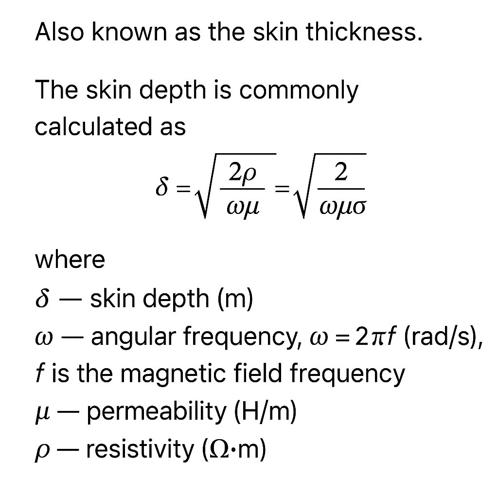
Skin Effect and Multi-Layer Hairpins
Because traction motors are driven by alternating current, the current distribution in a conductor is not uniform across its cross section; it tends to concentrate near the surface, an effect known as skin effect. The skin depth is inversely proportional to the square root of AC frequency, so at higher switching frequencies current flows more on the conductor surface. To address this while keeping slot fill high, the winding uses multi-layer hairpins. This approach minimizes DC resistance while increasing conductor surface area, yielding high slot fill and improved cooling.
Oil Cooling
BYD's flat-wire motor uses oil cooling. Oil is nonmagnetic and nonconductive, making it a suitable coolant with wider compatibility than water. The shaft in this motor allows oil to be pumped into the rotor core, where small holes at the edge spray oil onto the permanent magnets embedded in the rotor laminations. This approach provides cooling from the inside out, which is critical because irreversible demagnetization can occur if permanent magnets overheat. In future, permanent-magnet motors without this core oil-cooling feature would be considered less advanced.
Some manufacturers use ATF transmission fluid as coolant. ATF is formulated for torque converter and gearbox environments and is adequate for cooling a fixed motor housing. However, when ATF is sprayed into stator and rotor internals, its chemical properties can damage copper enamel and insulation paper. Insulation thickness and switching frequency are closely related, so many major manufacturers, including BYD, develop motor-specific oil formulations. Matching rotational speed and thermal control is necessary, and motor oil should not be changed arbitrarily during maintenance because it affects reliability and warranty.
The stator also embeds temperature sensors near the oil channels. Measuring temperature inside the stator is more useful than external case measurements for precise thermal control, and deeper, more accurate temperature monitoring allows safe full-speed operation.
Rotor Design
Removing the end cap reveals V-shaped permanent magnet segments inserted into the rotor slots.
BYD's rotor laminations use a combination of staking points and welding. When the rotor cuts magnetic flux, eddy currents form; welds and staking points can create closed paths for eddy currents, increasing iron loss and heating. Rotor heating is especially concerning because permanent magnets are sensitive to temperature-induced irreversible demagnetization.
However, BYD uses a new low-loss electrical steel grade for the laminations. This material, with higher internal impurity content and thinner lamination thickness, reduces eddy current effects and lowers iron losses and heating. In other words, BYD's choice of materials mitigates some disadvantages of the lamination joining method.
Overall, BYD's rotor design balances performance and cost. Some choices trade the highest possible technical sophistication for manufacturability and economy while meeting performance targets; this is a common engineering compromise.
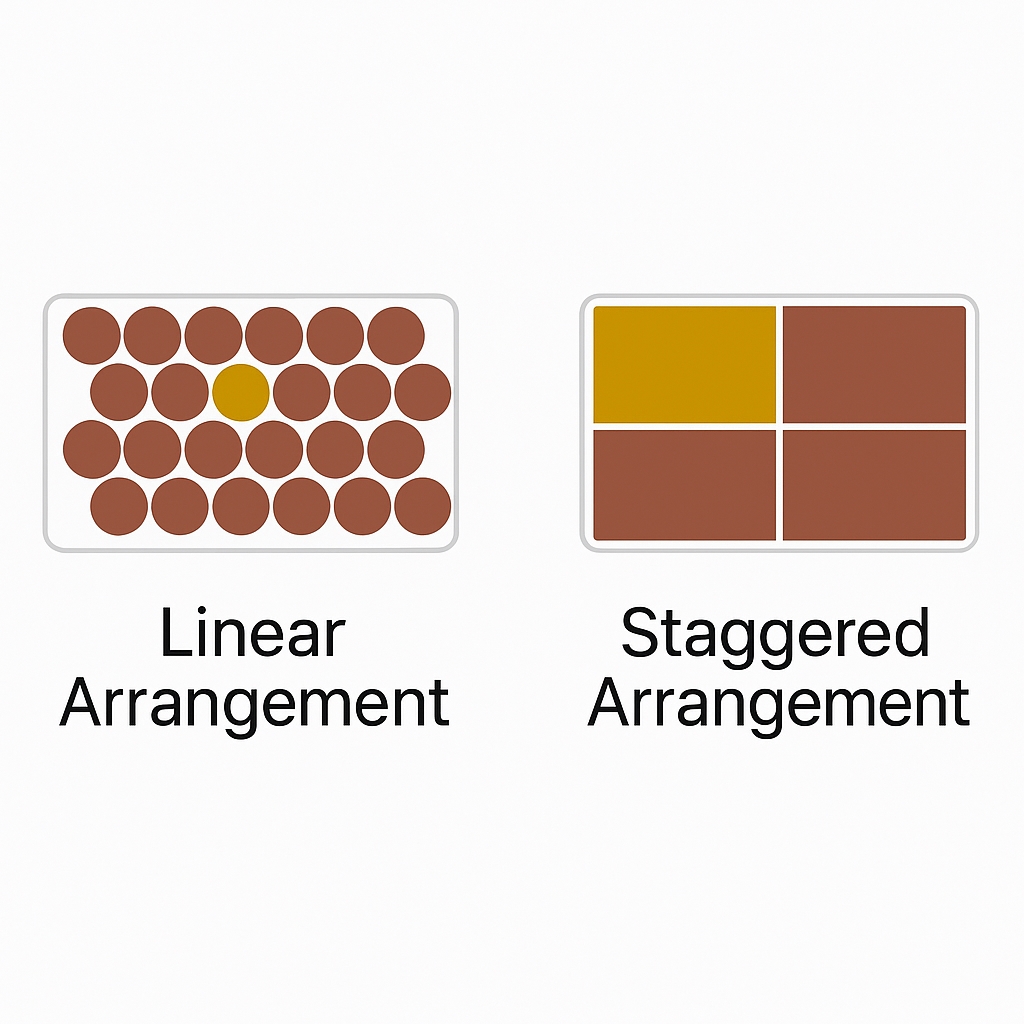
The permanent magnet segments are not continuous from end to end. BYD uses a segmented layout with side chamfers to reduce acoustic noise. Because a sinusoidal AC drive is synthesized from discrete switching of DC sources by the inverter, high-speed harmonic content creates noise. A segmented magnet layout smooths those harmonics similarly to how helical gears can be quieter than straight-cut gears.
Magnet Bridge and Gaps
The gaps around magnet segments exist because sintered neodymium-iron-boron magnets are difficult to machine into complex shapes. Leaving small voids is a practical solution, though some manufacturers use hybrid magnets or specialized adhesives to fill these gaps. A few companies produce mixed magnet solutions that combine sintered and bonded magnets to improve magnetic flux. Some manufacturers in China, such as SAIC and FAW, also use similar techniques.
The thin region around the magnet edges is the magnetic bridge. It is designed to provide mechanical integrity during high-speed rotation while remaining thin enough not to overly restrict magnetic flux leakage.
Magnetic Field Visualization
The team used a magnetic field observation film to visualize flux lines. The film changes color according to the angle of the magnetic field: dark where flux is perpendicular to the film and light where flux is parallel. The motor shows a 4-pole, 8-pair layout overall, with two parallel flux lines at pole edges due to adjacent magnets having parallel field regions.
An important concept is leakage flux. Most useful flux lines penetrate radially and cut the stator windings; this is effective flux. Flux lines that do not exit the rotor are leakage flux and cannot be utilized. The observation film indicates that BYD has optimized leakage so that a larger proportion of flux participates in cutting the stator coils.
Reduction Gearset
The eight-in-one assembly yields a gearbox reduction of around 11:1. Some readers may ask why Tesla's reduction ratio is around 9.3:1. The higher BYD ratio favors energy-efficient output and reduces stress on gear teeth, which can improve reliability. However, higher tooth-face pressure increases gear manufacturing cost. There is no absolute right or wrong choice; it depends on the manufacturer's target tradeoffs. BYD's design choices reflect a mid-market positioning intended to meet broader customer requirements and to deliver higher motor power density without high price premiums.
Quantified Design Summary
| Quantified Value / Assessment | Advantages / Design Benefits | Disadvantages / Improvement Suggestions | |
|---|---|---|---|
| Stator slot count | 72 slots | Concrete specification | Concrete specification |
| Stator winding | 6-layer flat-wire, oil-cooled | Good cooling performance | Complex manufacturing |
| End-turn length | Front 47.53 mm / Rear 33.09 mm | Moderate length; includes protective frame | Concrete specification |
| Rotor pole count | 8-pole, double V arrangement | Favorable CT factor 8 | Design prioritizes energy efficiency |
| Rotor segmentation | 5-layer V-shaped stagger | Good acoustic performance | Complex manufacturing |
| Magnet type | NdFeB sintered magnets | Simpler process | Side gaps could be optimized for magnetic density |
| Lamination thickness | 0.20 mm low-loss electrical steel | Iron loss optimization | Complex processing |
| Magnetic bridge size | Largest V min 1.03 mm; smallest V min 0.98 mm | Iron loss optimization | Complex processing |
Permanent Magnets and Leakage Flux
BYD optimizes leakage flux so that more magnetic lines exit the rotor and participate in cutting the stator windings, improving overall efficiency. The magnet segmentation and side chamfers reduce noise while avoiding excessive mechanical mass at the magnet edges.
Conclusion
The BYD Seal motor demonstrates several practical engineering tradeoffs: multi-layer flat-wire hairpin windings for higher slot fill and reduced copper loss, oil cooling to protect magnets and control temperature, segmented rotor magnets to reduce noise, and low-loss thin laminations to mitigate eddy current losses even with mechanically joined laminations. These choices balance performance, cost, manufacturability, and reliability to meet the vehicle's targeted market positioning.