Overview
PLC programming is often done using an intuitive approach based on the circuit designer's own experience, so programs tend to be subjective and direct. A period of trial-and-error and debugging is commonly required before the program meets the required behavior. As a result, programs vary between designers and their readability can be low for users or maintenance personnel.
This article uses the "Three-phase induction motor fault alarm control" circuit as an example to show the process of converting a traditional electrical wiring diagram into a PLC ladder diagram, and to outline a practical program-design workflow for similar circuit conversions.
1. Traditional wiring diagram
The known control circuit for the three-phase induction motor fault alarm is shown in Figure 1.
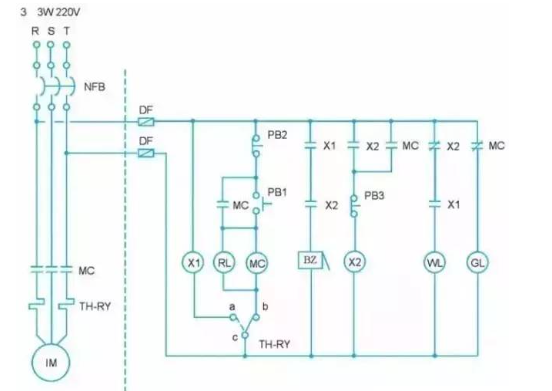
2. Operation description
- When the power supply is normal, only the green lamp gl is on and the motor does not run.
- Press the start button pb1: the contactor mc energizes, the motor starts immediately, indicator light rl turns on, and green light gl turns off.
- Press the stop button pb2: contactor mc de-energizes, the motor stops, indicator light rl turns off, and green light gl turns on.
- If the motor trips due to overload or another fault, the thermal relay th-ry operates: the motor stops, the buzzer bz sounds an alarm, indicator rl turns off, and green light gl turns on.
- Press button pb3 to silence the buzzer bz: white lamp wl turns on, green lamp gl remains on, and red lamp rl stays off.
- After the fault is cleared, reset the thermal relay th-ry using its reset lever: white lamp wl turns off, green lamp gl turns on, red lamp rl stays off, and the motor can be restarted.
3. I/O encoding
In the realm of Industrial Control, using a PLC replaces hardware wiring with software. The PLC cannot replace the main power circuit, but it can replace the control circuit. The first step when converting a traditional wiring diagram to a ladder diagram is I/O encoding: assign each input and output component from the wiring diagram to a corresponding PLC external input/output terminal number, and decide whether each external input component is wired using an a-contact or b-contact method.
(a) External wiring using a-contact method.
(b) External wiring using b-contact method.
4. PLC external wiring diagram
After I/O encoding and deciding the a/b contact wiring methods, the PLC external wiring diagram can be drawn. The example shown is for the Vigor-VB series PLC using NPN wiring; it is also possible to parallel the 24 V terminal with the S/S terminal.
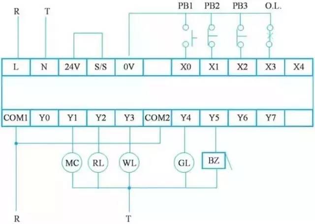
Figure 2: PLC external wiring diagram
5. PLC ladder diagram
The program design steps to convert a traditional wiring diagram into a ladder diagram are as follows:
Step 1: Redraw the control circuit to match ladder format
PLC ladder diagrams require contacts to appear before output coils, with coils at the end of the rung. First, redraw the wiring diagram to reposition contacts and coils so the diagram conforms to ladder-diagram conventions. The redrawn wiring diagram is shown in Figure 3.
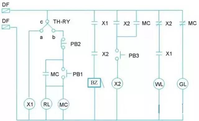
Figure 3: Redrawn control wiring diagram
Step 2: Replace components with I/O codes
Replace the input/output components in the redrawn diagram with their I/O-coded component numbers. Note that the c-a and c-b contacts of th-ry should be separated into independent control circuits, as shown in Figure 4.
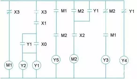
Figure 4: Wiring diagram after I/O encoding
Step 3: Rotate and flip to produce the ladder layout
Rotate the diagram in Figure 4 90 degrees to the left, then flip it vertically to form the PLC ladder diagram. Adjustments may be required because some contact and coil notations may not match typical programming software formats; make those corrections as needed.
Step 4: Draw the ladder in programming software
Use PLC programming software to draw the ladder diagram. The resulting ladder should match the adjusted diagram from the previous step, as shown in Figure 6.
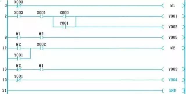
Figure 6: Ladder diagram drawn in programming software
6. Instructions
The ladder diagram can be translated into PLC instructions for the target PLC. The instruction mapping for this example is shown in Figure 7.
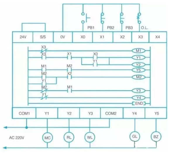
Figure 7: Instruction list converted from the ladder diagram
7. PLC wiring and ladder summary
After fully converting the traditional wiring diagram, the PLC external I/O wiring and the ladder diagram together replace the original hardware relay wiring. The PLC-based external I/O wiring and ladder diagram for this example are shown below.
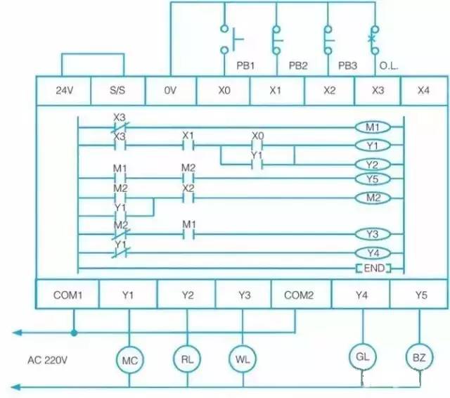
Figure 8: PLC external I/O wiring and ladder diagram after conversion
8. Conclusion
The purpose of PLC development was to replace relay-based sequential control by using software programs instead of hardware wiring. Changing the software program changes the control sequence, allowing different control requirements to be implemented without changing the wiring.
Modern PLCs are built on traditional relay control concepts, symbolizing relay contacts and coils. Converting these into ladder diagrams or instruction lists enables the desired control logic to be implemented in software.