5 Huawei - CN115333265A
Patent CN115333265A
The cooling oil enters the housing 1 through the mid-section inlet 11. Unlike other mid-inlet schemes, this housing includes an annular channel 12. The outer diameter of the stator core at the mid section is the same as at other sections. The inlet 11 directs coolant onto the surface of the stator core 21. Multiple grooves on the stator core surface form axial cooling channels a. The end faces 13 and 14 of the stator core laminations have guide grooves forming radial cooling channels b. A first end plate 23 and a second end plate 24 are located at the two axial ends of the stator core 21; these end plates have spray holes 232 and 241 respectively, which spray coolant onto the windings.
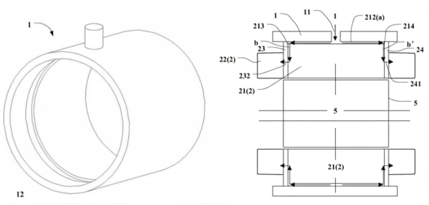
Figure 5.1 Cooling housing. Figure 5.2 Oil flow diagram.
The stator core uses four types of silicon steel laminations: first type 215, second type 216, third type 217, and fourth type (end plate) 23. From the middle to the ends, the stacking order is: first type, third type, second type, fourth type.
The first type lamination 215 has several first notches 2151 on its outer diameter. The first notches 2151 of multiple first type laminations connect to form slots 212 on the stator core 21. These slots, together with the housing 1, form the axial cooling channels a along the core surface.
The second type lamination 216 has nine arc-shaped second notches 2161 which, when stacked, form the radial cooling channels b.
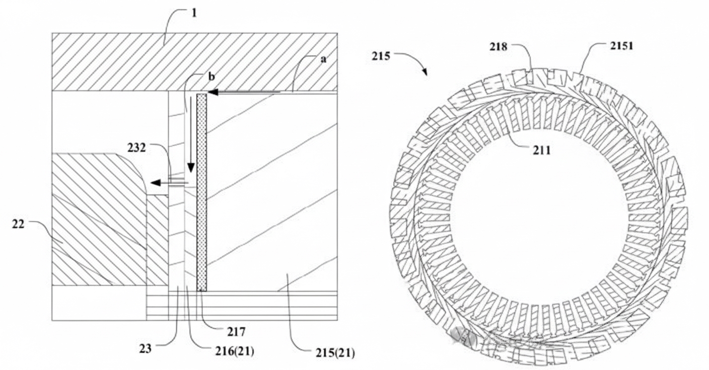
Figure 5.3 Lamination stacking relation. Figure 5.4 First-type lamination.
The third type lamination 217 has nine rectangular third notches 2171. These third notches partially overlap with at least two adjacent second notches 2161 to connect adjacent radial coolant channels b. This arrangement helps equalize flow from the first spray hole 232 that serves adjacent radial channels, improving circumferential uniformity of cooling for the coil windings 22. The third lamination 217 also includes a fourth notch 2172 positioned opposite the first notch 2151, ensuring communication between axial coolant channel a and radial coolant channel b.
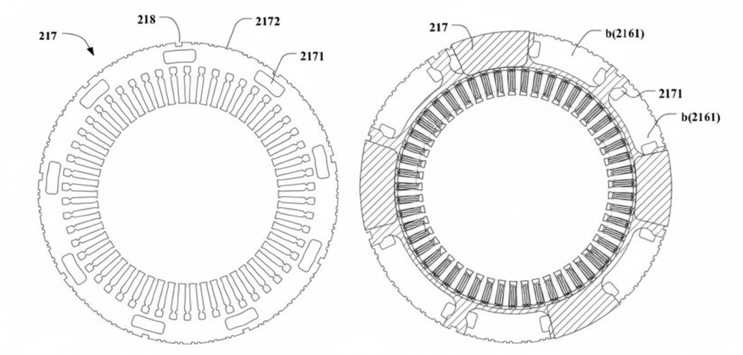
Figure 5.5 Third-type lamination. Figure 5.6 Second- and third-type lamination assembly.
The fourth type lamination 23 has spray holes 232 located above the slot bottoms and arranged uniformly around the circumference, so that oil exiting radial channels b is sprayed onto the windings via these spray holes. The fourth type lamination 23 may be replaced by a plastic or aluminum end plate.
Optional inclined holes can be added to the end plate 23 to increase coolant coverage and improve winding cooling. Alternatively, the lower spray holes can be omitted so that oil sprayed onto the upper windings flows downward by gravity to cool lower windings, improving overall cooling efficiency.
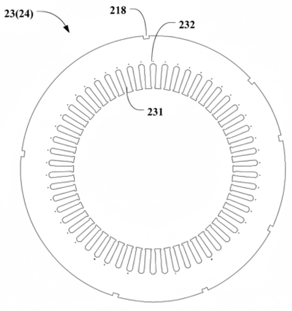
Figure 5.7 Omit lower spray holes.
The spray nozzle component 237 can be made detachable from the end plate body 236. During varnish dipping, low-viscosity liquid varnish can flow by capillary action and block small spray holes 232 on end plate 23. In this embodiment, the first spray hole 232 is formed in the detachable nozzle component 237, so varnish dip can be performed before assembling nozzle component 237. At that time the outlet opening is larger and is less likely to be blocked. The nozzle component 237 is then assembled so its first spray hole 232 aligns with the outlet, enabling coolant flow.
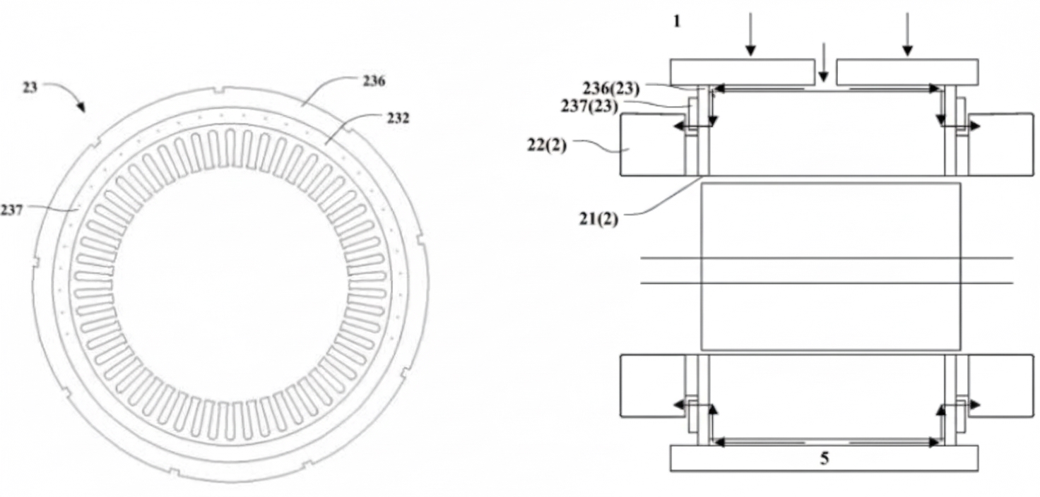
Figure 5.8 Detachable end plate. Figure 5.9 Detachable end plate assembly cross-section.
By changing notch positions or stacking order of laminations, multiple cooling schemes can be constructed; details are described in the patent.
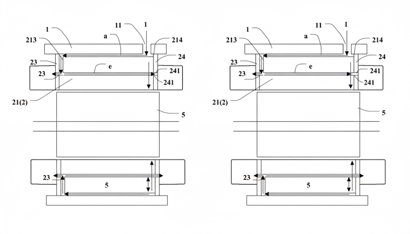
Figure 5.10 Optional scheme 1. Figure 5.11 Optional scheme 2.
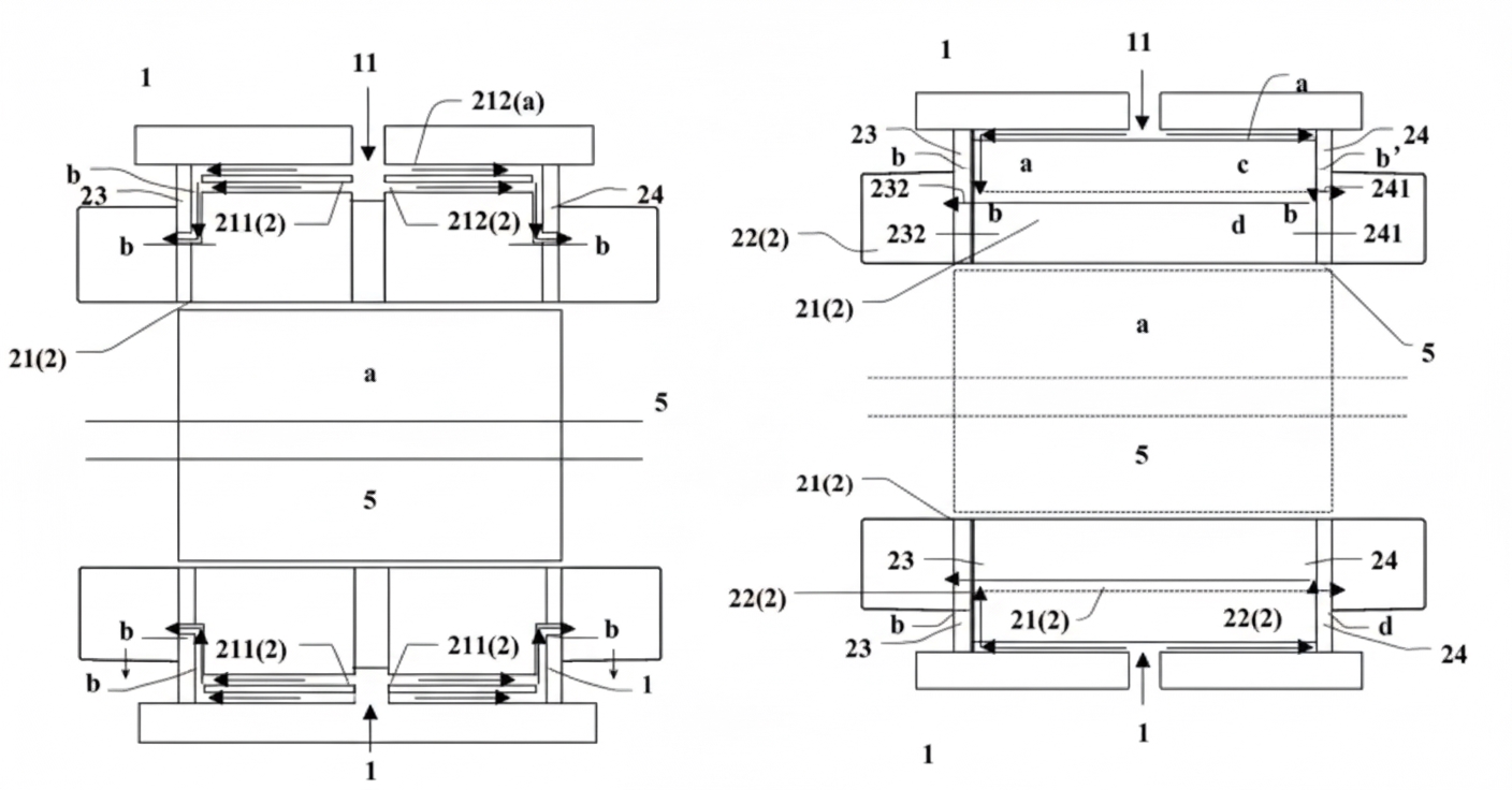
Figure 5.12 Optional scheme 3. Figure 5.13 Optional scheme 4.
Summary
This scheme locates most notches of the first laminations 215, second laminations 216, and end plate 23 on the circumferential side of the stator core 21, minimizing damage to the core and preserving electromagnetic performance. The detachable nozzle components prevent spray holes from being blocked by varnish. The scheme also omits additional spray parts such as spray rings and tubes. By using second and third notches to interconnect channels, circumferential pressure distribution becomes more uniform, resulting in more even flow from circumferential spray holes.
6 Huawei - CN116865465A
Patent CN116865465A
Huawei made improvements to the earlier patent CN115333265A. This cooling system has inclined first cooling outlets 11 at the stator yoke and second cooling outlets 12 above the slot bottoms. Multiple first cooling holes are arranged adjacent to multiple second cooling holes; each radial channel connects a first cooling hole and a second cooling hole. The oil path is as follows:
Cooling oil enters the housing through inlet 501, travels through the housing annular channel 502, and is introduced onto the surface of first-type stator core T1. It flows along multiple axial cooling channels D1 on T1 toward both axial ends. Oil flowing to the front end passes through second-type core T2 and third-type cores (end plates) T31 and T32 and is inclined-sprayed from the first cooling holes 11 onto the top of the windings. Oil flowing to the rear end passes through radial channels 15 formed by guide grooves in the second-type core T2 and exits via the second cooling holes 12, re-entering axial cooling channels D2 on core T1. The second-type core T2 and third-type cores T31 and T32 are assembled with rotational offset to form serial cooling channels 11 and 12 at both winding ends.
The stator core uses three types of laminations: first-type T1, second-type T2, and third-type (end plate) T3. The third structural T3 includes inner T31 and outer T32 structures. From the middle to the ends, the stacking is: first type, third type, third type.
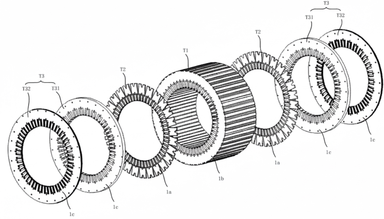
Figure 6.1 Core exploded view.
The first-type lamination T1 has both first cooling holes 11 and second cooling holes 12, with each first hole 11 adjacent to a second hole 12, forming cooling channels D1 and D2. The first cooling hole 11 can be an open slot or a closed slot. Closed slots offer better sealing but reduce local external diameter strength, increasing risk of core cracking. In actual products the open-slot arrangement in Figure 6.7 was chosen. There are two types of first cooling holes, 11a (cooling slot) and 11b (welding slot). A protrusion 11 in 11a separates the first cooling hole 11 into two parts, changing the flow cross-section and flow rate.
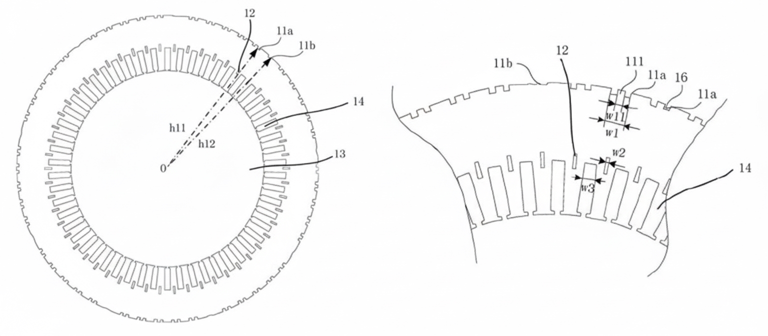
Figure 6.2 First-type lamination multiple slots. Figure 6.3 First-type lamination detail.
The second-type lamination T2 also has first cooling holes 11 and second cooling holes 12. One first cooling hole 11 is connected via a radial channel 15 to one of two adjacent second holes 12, so first and second cooling holes that are connected by radial channels alternate with those that are not connected, forming an alternating arrangement.
The second-type laminations T2 are assembled with rotational offsets at both ends of first-type laminations T1 to form U-shaped cooling channels in sequence at front and rear. For example, first-type lamination 1b's first cooling hole 11 is connected on one side to second lamination 1a's second cooling hole 12 while the opposite side remains unconnected.
The third-type lamination T3 has first cooling holes 11 and second cooling holes 12. The distance between the first cooling holes 11 and the center hole 13 decreases circumferentially along stator core 10. Non-rotational press-fit produces T31 which forms horizontal channels D1; rotational press-fit produces T32 which forms inclined channels D1. To form inclined spray holes, more first cooling holes 11 can be added to T3 surface or the end plates can be manufactured as integral plastic or aluminum parts.
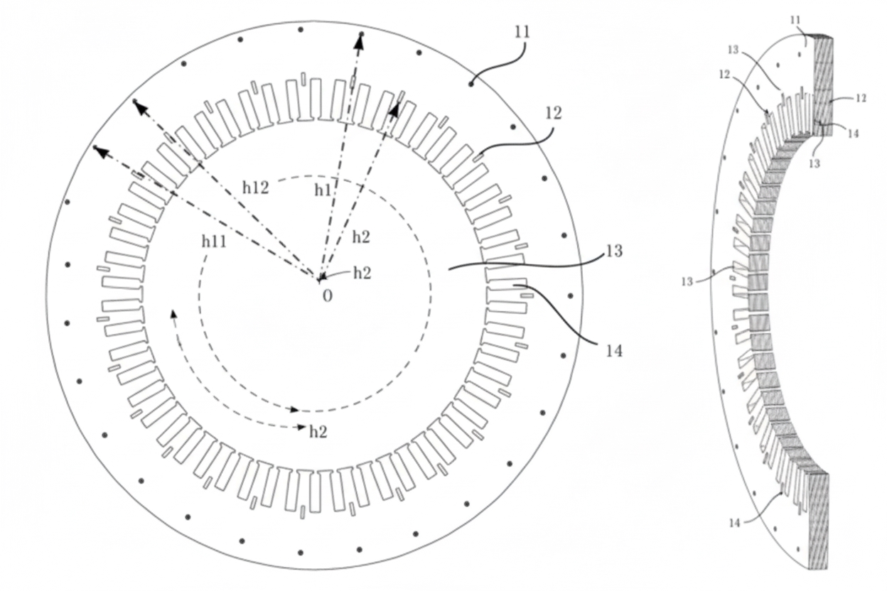
Figure 6.4 Third-type lamination. Figure 6.5 Third-type lamination assembly.
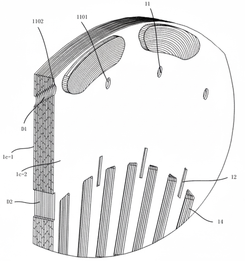
Figure 6.6 Third-type lamination assembly detail.
Summary
This patent creates two layers of cooling channels across the stator core radial direction. Radial channels connect first and second cooling holes, allowing coolant to flow between layers and improving cooling efficiency and motor heat dissipation. Stacking multiple third-type laminations with offsets forms inclined radial channels that can spray coolant accurately onto winding ends. Compared with the previous scheme, this uses one fewer lamination specification and increases coolant utilization. However, it can cause large local flow resistance, especially for coolant that must flow from the core surface axial channels into slot-bottom radial channels against gravity, which may reduce flow at lower second spray holes.
7 Xiaomi - CN116014928A
Patent CN116014928A
This patent uses cooling oil rings. A first oil ring 21 and a second oil ring 22 are located at the front and rear ends of the stator core 1 and are coaxial with the stator core. Each oil ring has multiple oil inlet channels 23 and multiple oil outlet channels 24, and these channels communicate with axial spray holes formed in the stator core to form cooling channels 12.
Cooling oil enters through housing inlet 201 and flows into cooling channel 12 via a first inlet channel 231 of the first oil ring 21. Oil moves along the length of the cooling channel 12 and exits at the other end, where it can enter the second oil ring 22 through inlet channel 232. Because second inlet 232 communicates with adjacent second outlet 242, oil can be discharged from the second oil ring 22 via outlet 242 and then return via another cooling channel 12 to first outlet 241. The oil rings also have spray holes through which oil is sprayed onto the winding ends.
The oil rings 21 and 22 are made from oil- and high-temperature-resistant plastics. Their inner circumferential walls have first spray holes 251, 252; first spray hole 251 communicates with first outlet 241, and second spray hole 252 communicates with second outlet 242.
The outer peripheral wall of the oil ring has an annular groove 27 on the side away from the stator core 1. The annular groove 27 communicates with multiple inlet channels 23 so that coolant can be evenly distributed to the stator core cooling channels 12, enabling uniform cooling of the winding ends and stator core.
The oil ring includes locating posts 26 that engage corresponding holes on the stator core end, simplifying installation and providing reliable mechanical connection.
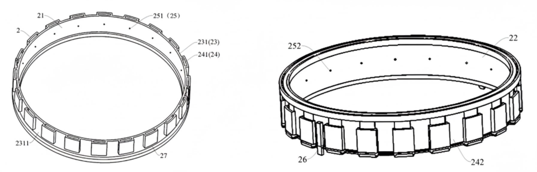
Figure 7.1 First oil ring face A. Figure 7.2 First oil ring face B.
Cooling channels 12 can be arranged parallel to the stator core axis, have an angle relative to the axis, or be wave-shaped or serpentine to lengthen the cooling path inside the stator core and improve cooling performance.
Summary
This cooling structure is simple: using a single lamination specification and two oil rings, it achieves stator core cooling and end-spray cooling. By offsetting lamination stacking and assembling front and rear oil rings with rotational offset, the oil path forms bidirectional cooling channels: front oil ring → core channels → rear oil ring → core channels → front oil ring. This greatly increases flow path length and heat dissipation area. Oil ring installation via locating pins is simple and reliable, although achieving consistent front-to-rear winding cooling is challenging.
8 Xiaomi - CN116613907A
Patent CN116613907A
To improve uniformity of cooling at the front/rear ends and circumferentially, this design routes coolant from the housing first inlet 41 to the stator rear, then along the stator core 21 toward both sides. The coolant enters oil rings at both sides and is sprayed over the entire circumference of the stator windings 22, cooling both stator core 21 and windings 22.
The stator is built from two types of laminations: first-type 211 and second-type 212. The first lamination 211 includes eight outlet holes 2110 and assembly holes 2111 for fixing the oil rings. Assembly holes 2111 match with installation holes 14 of oil ring 1; when oil ring 1 is fixed at both ends of stator core 21, coolant from the stator core surface is introduced into the oil rings.
The outer ring of the second lamination 212 has multiple circumferentially spaced ribs 2121. Adjacent ribs and the housing 4 form channels 203. Any channel 203 in any second lamination 212 can function as a second inlet 2120.
Multiple second laminations 212 are grouped into lamination groups 200. The channels of second laminations within a lamination group 200 connect to form inclined channels 201. Channels of adjacent lamination groups 200 connect to form staggered channels 202. The inclined channels 201 guide coolant axially to fill the second laminations within a group; the staggered channels 202 guide coolant circumferentially to connect second laminations of adjacent groups. The combination of inclined and staggered channels allows coolant from any inlet to flow and cover the entire circumferential surface of the stator core 21, achieving 360° uniform cooling of the stator core.
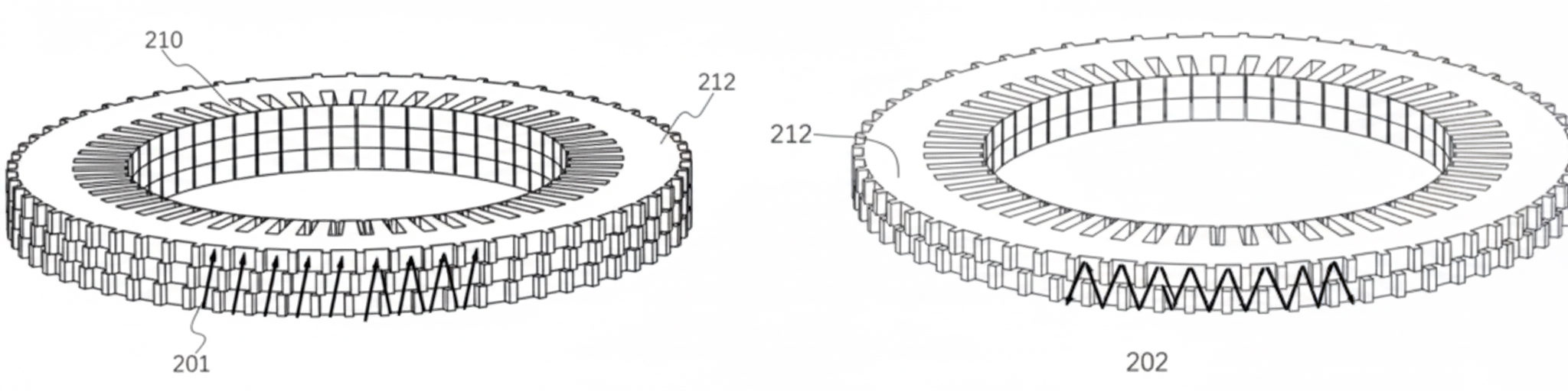
Figure 8.1 Inclined stacking of second laminations. Figure 8.2 Staggered stacking of second laminations. Figure 8.3 Cooling channel schematic.
The oil ring body 100 has a closed mating face 11. The oil ring can be injection molded to form oil chambers and then sealed by welding end cap 101 to form closed oil cavities. Assembly gaps 10 are provided between adjacent oil chambers. The oil ring 1 has inlet holes 12 located on mating face 11 to connect with stator outlet 2110, and spray holes 13 on the oil chamber wall facing the windings 22. Coolant entering the oil ring can be sprayed over the windings' entire circumference.
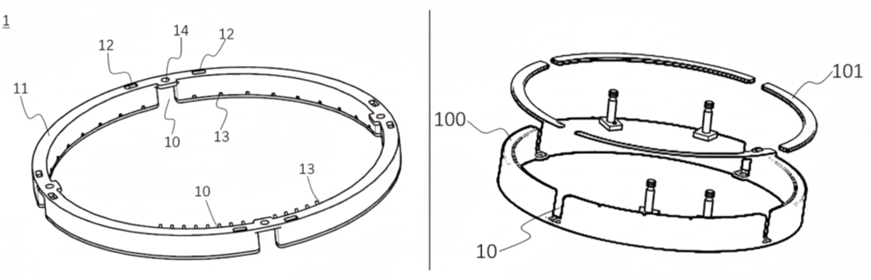
Figure 8.4 Oil ring assembly. Figure 8.5 Oil ring with welded end cap.
Summary
Xiaomi's design uses two lamination types and staged stacking and rotation to form varied coolant flow paths, improving stator core cooling. Inclined channels increase the effective heat transfer area compared with straight channels. Staggered channels change coolant direction so that coolant from any inlet can cover the entire stator circumference, achieving 360° uniform cooling. This improves cooling uniformity, reduces thermal aging failure risk of the drive motor, and supports higher power and torque density.