General Wiring Guidelines
1. Follow the diagrams. Before wiring, read the drawings carefully and understand the designer's intent. Do not rely solely on personal experience. If any discrepancy or ambiguity is found, confirm with the designer before starting work.
2. Keep wiring order clear and verifiable. Wiring procedures should be simple and easy to inspect. In practice this is often neglected, with terminals connected quickly and covers closed without verification.
3. Learn wiring techniques and use appropriate tools. Examples and common questions are provided below.
Q: Handling many terminals in a PLC cabinet
When assembling PLC cabinets, terminal blocks and wire terminals are abundant. Poor handling can cause loose connections or frayed conductors. Should single-core wire insulation be stripped and the conductor inserted directly, or should pin ferrules be used, or should the conductor be tinned?
A: For single-core wire, strip and insert directly into the terminal. For stranded wire, use cold-crimp ferrules. Tinning is not recommended.
Q: Distributing common and supply lines across many PLC expansion modules
When the PLC has many expansion modules, how should common and power distribution be handled? Should the common/power be daisy-chained from module to module, or should it be routed to terminal blocks and bridged there?
A: For field maintenance convenience, distribute power and commons at terminal blocks and short them there, then route marked wires to each device. Use wire markers or clearly mark terminal destinations. Avoid daisy-chaining power from one point to another, and avoid connecting more than one conductor under a single terminal screw. For power terminal rails, prefer fused terminals or terminals with disconnectible links between upper and lower levels; these make fault locating much easier.
1. PLC External and Internal Circuits
1. External wiring
Figure 1 shows an electrical control circuit for direct-on-line (DOL) motor start using contactors. The control logic is implemented by the AC contactor coil KM, pilot lights HL1 and HL2, the normally closed thermal relay contact FR, the stop button SB2, the start button SB1, and the contactor auxiliary normally open contact KM wired together.
After closing the main switch QS, pressing start SB1 energizes coil KM which self-latches. This closes the auxiliary contact and the main contactor, lighting HL1 and starting motor M. Pressing stop SB2 de-energizes coil KM, HL1 extinguishes, and motor M stops.
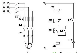
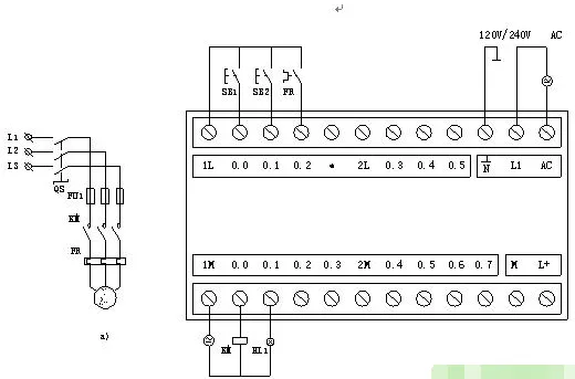
Figure 2 shows external wiring when a SIEMENS S7 series PLC is used to implement the same DOL motor start control. The power circuit remains the same. The thermal relay contact FR, stop button SB2, and start button SB1 are connected to the PLC input terminals as input devices. The contactor coil KM and pilot lights HL1, HL2 are connected to the PLC output terminals as output devices. Control logic is implemented by the user program stored in the PLC program memory, following the DOL control requirements.
2. Establishing the internal I/O image area
The PLC memory allocates an I/O image area to store the states of I/O signals, called the input image registers and output image registers. Other programming elements also have corresponding image registers called element image registers.
The size of the I/O image area is determined by the PLC system software. Each physical input point corresponds to a bit in the input image area, and each physical output point corresponds to a bit in the output image area. The addressing numbers for system I/O points correspond to addresses in the I/O image area.
During operation, the PLC stores sampled input states in the input image area and stores the computed results in the output image area. When executing the user program, references to equivalent input or output contacts or coils use the I/O image area rather than direct interaction with external devices.
Using an I/O image area makes PLC operation dependent on memory state rather than direct hardware state, which speeds program execution and isolates the control system from external interference, improving noise immunity.
3. Internal equivalent circuit
Figure 3 shows the PLC internal equivalent circuit. Take start button SB1 as an example: its input interface I0.0 is connected to an input image flip-flop I0.0. When SB1 is closed, flip-flop I0.0 is set to logic 1. This logic 1 can be referenced in the user program as contact I0.0. Thus, the I0.0 contact reflects the state of SB1: closed yields logic 1; open yields logic 0.
The I0.0 flip-flop behaves like a soft relay coil inside the PLC. A contact that directly references the I0.0 coil is equivalent to a normally open contact controlled by that soft coil.
Similarly, stop button SB2 is connected to an input flip-flop I0.1. When SB2 is closed I0.1 equals 1, otherwise 0. The user program commonly uses the inverted state of I0.1 as a contact, making I0.1 act like a normally closed contact. Output contacts Q0.0 and Q0.1 are physical normally open contacts of PLC internal relays; when closed, they energize the external KM coil or pilot lights HL1. The PLC output terminals include a common terminal COM for the output supply.
2. PLC Control System
Using a PLC to implement DOL motor start keeps the main power circuit largely unchanged while replacing the hardwired control circuit with a PLC-based control system.
1. PLC control system composition
Figure 4 shows the basic composition of a PLC control system for a DOL motor start. It can be divided into three parts: input circuits, internal control circuits, and output circuits.
Input circuits
The input circuit delivers control signals to the PLC. Input devices include buttons SB1 and SB2 and the normally closed thermal relay contact FR. External control signals are mapped to input relays in the PLC. Each input relay can provide any number of normally open and normally closed contacts for use in the PLC program.
Output circuits
The output circuit converts PLC output signals to signals capable of driving the KM coil and pilot light HL1. The PLC internal control circuit contains many output relays. Each output relay provides programming contacts and a physical normally open internal contact connected to the output port. This internal contact drives external loads such as the KM coil and HL1, while the KM main contact in the power circuit controls motor M. The load drive power is provided from the external power supply; the PLC output ports include the COM common terminal for the output supply.
Internal control circuit
The internal control circuit is formed by the user program written to meet the actual motor control requirements. It computes and processes input and output signal states according to the programmed logic, producing output control signals that drive output devices such as motor M and pilot light HL1.
User programs are written into the PLC user program memory via a PC communication link or a programming device. Modifying the user program requires updating memory contents only and does not change the PLC internal wiring, enabling flexible control.
2. PLC ladder diagram
A ladder diagram models PLC internals as equivalent control circuits composed of soft relay coils, normally open contacts, normally closed contacts, and function blocks. Figure 5 shows common ladder symbols:
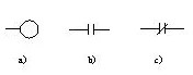
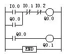
Figure 6 is a ladder diagram for the DOL motor start. It is composed of the FR normally closed contact, SB2 normally closed button, a parallel unit of KM auxiliary normally open contact and SB1 normally open button, and the KM coil. The ladder form resembles the hardwired contactor control schematic but differs in many important ways.
Differences between ladder elements and physical electrical elements
1. Physical structure: Ladder coils and contacts are functionally equivalent to electrical coils and contacts, but physically they are bits in memory, not physical components.
2. State representation: The open/closed state of ladder elements corresponds to stored bit values. A stored bit of 1 means the element is "closed"; 0 means "open". This differs from physical device states.
3. State switching process: Changing a ladder element state is an operation on memory bits. Setting a bit to 1 performs a make operation; clearing a bit performs a break operation. These memory operations have no inherent time delay. Physical coils and contacts require mechanical switching time and usually follow a sequence of open then close with delay.
4. Contact multiplicity: In ladder logic, a single input bit can be copied or inverted and stored into many other bits, effectively creating unlimited virtual contacts controlled by the same logical input. However, PLC coils are typically referenced only once; reuse of the same coil address should be done with care. In contrast, physical relays have a limited number of contacts.
Ladder diagram lines are drawn from the left rail to the right rail, with parallel units typically on the left, the output coil on the right, and series elements in the middle.