Graph program setup
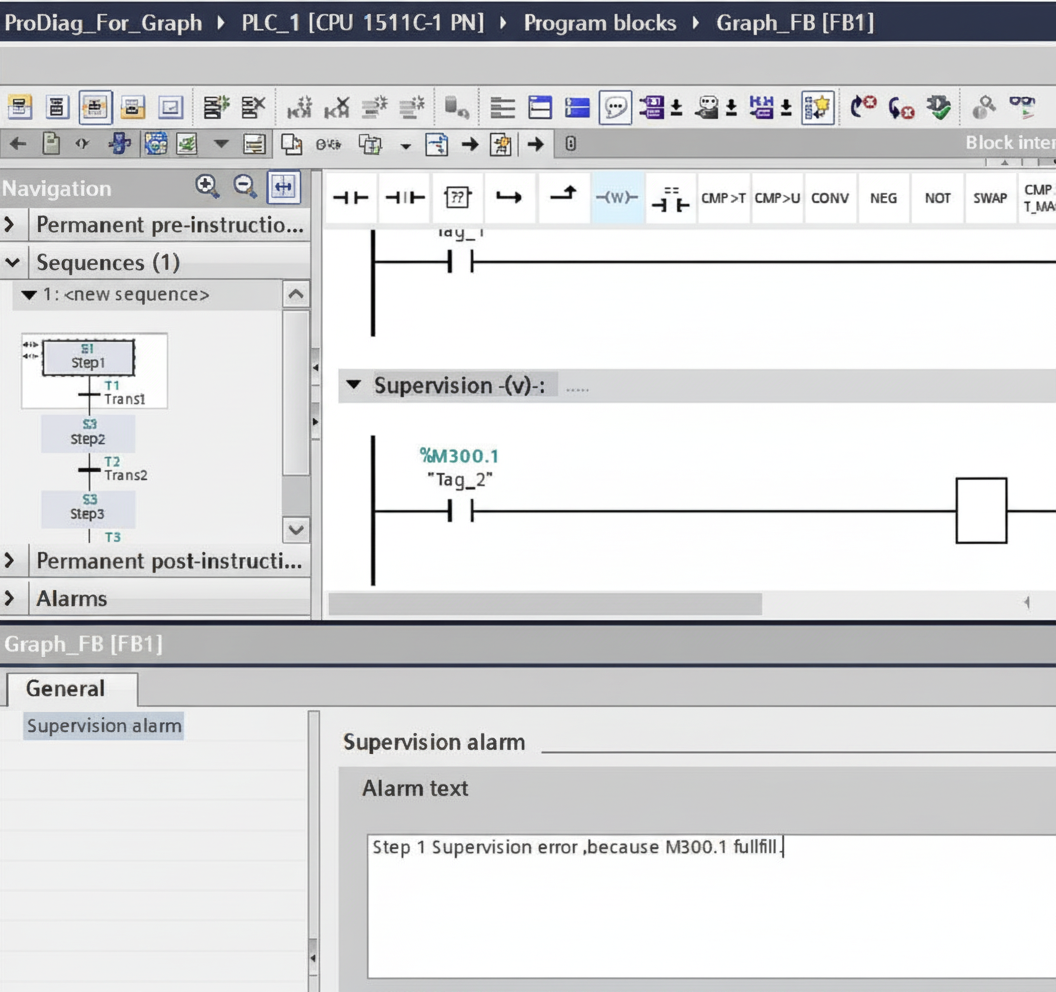
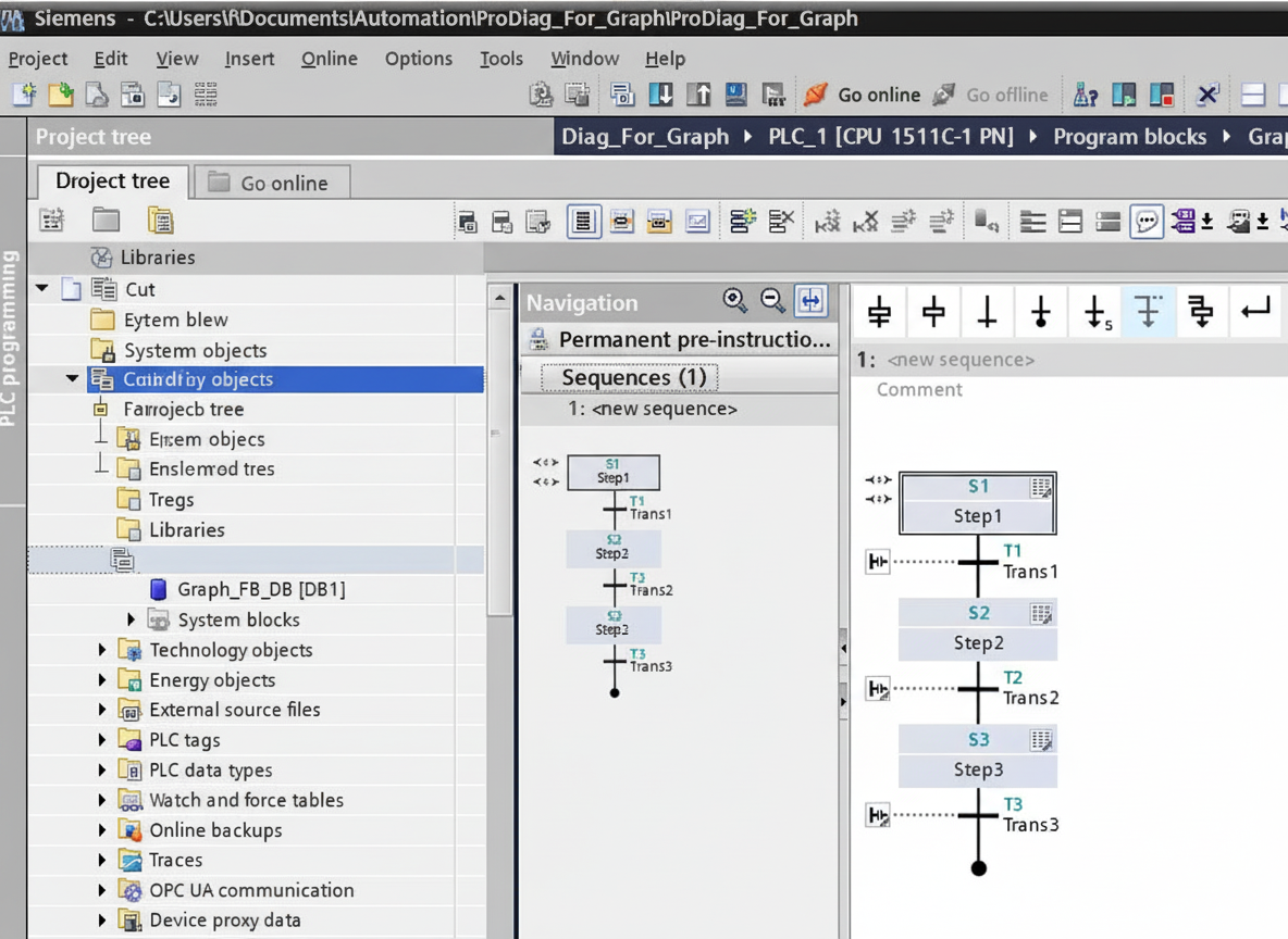
1. Create a Graph program. In the steps, add interlock and monitoring conditions.
2. In the monitoring properties you can edit the related alarm text content.
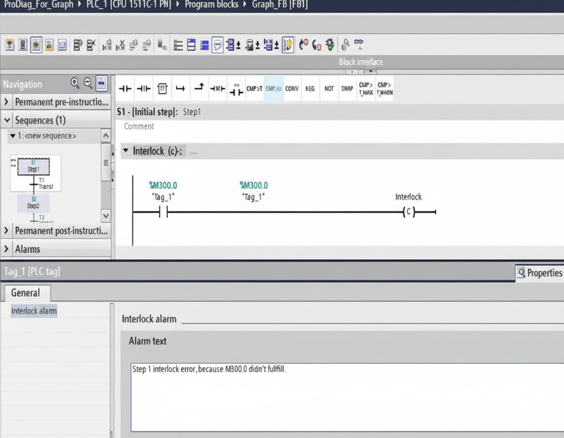
3. The monitoring properties allow additional editing of alarm text details.
4. Then configure the Alarm text structure.
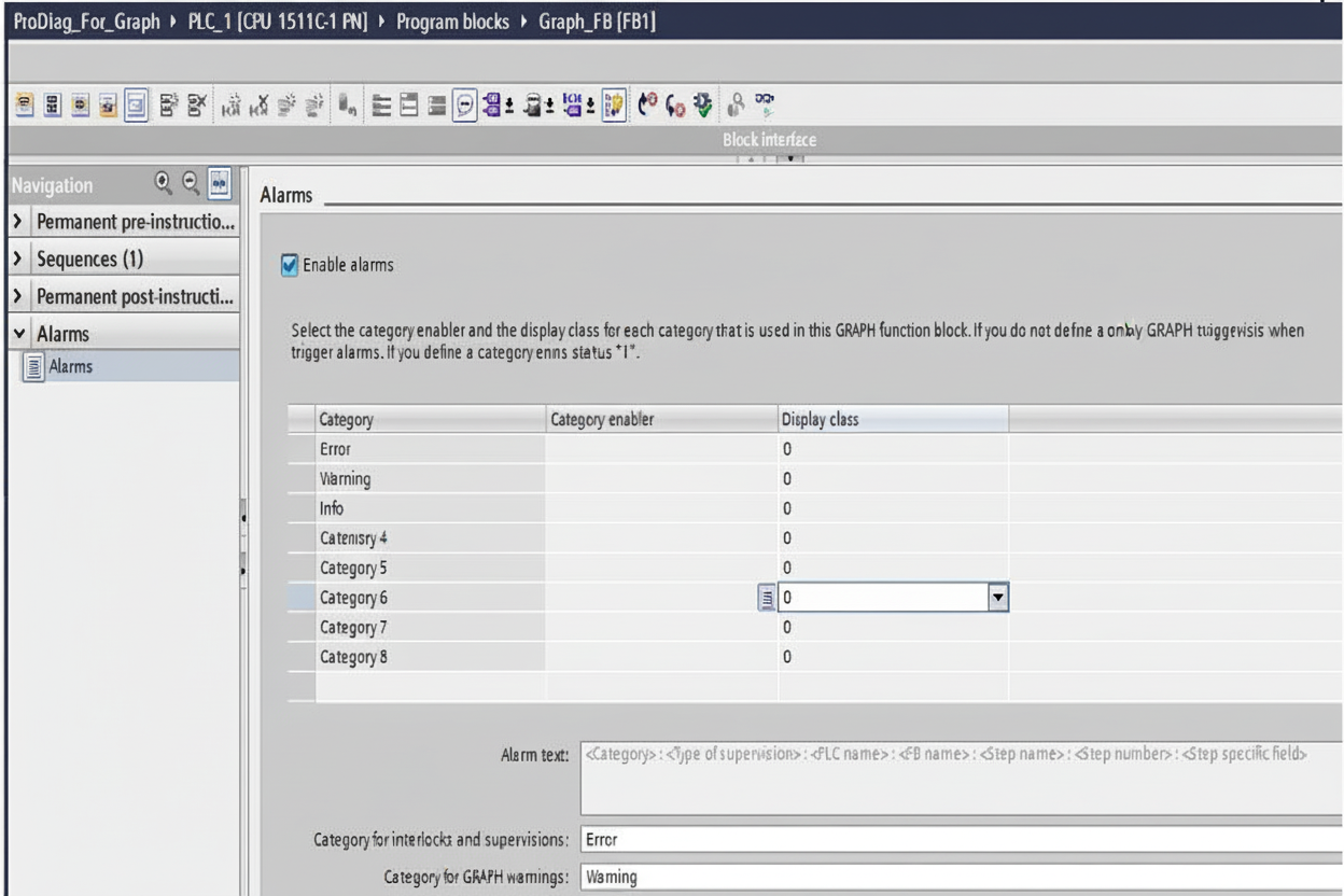
In the table, the Category enabler lets you select a variable. When the variable is True, that alarm category is enabled; when False, that category is disabled. By default, no variable is selected, which enables all alarm categories.
5. "Alarm text" is the configured alarm text structure. You can configure it via the green arrow.
If there are no special requirements, using the default structure will display detailed program information.
6. Finally, in the Graph Edit menu select "Internal parameters visible/accessible from HMI". This allows the HMI to directly access the Graph background data block contents.
HMI settings and control configuration
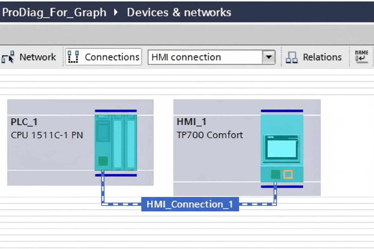
1. Add a Comfort screen, then connect it to the CPU.
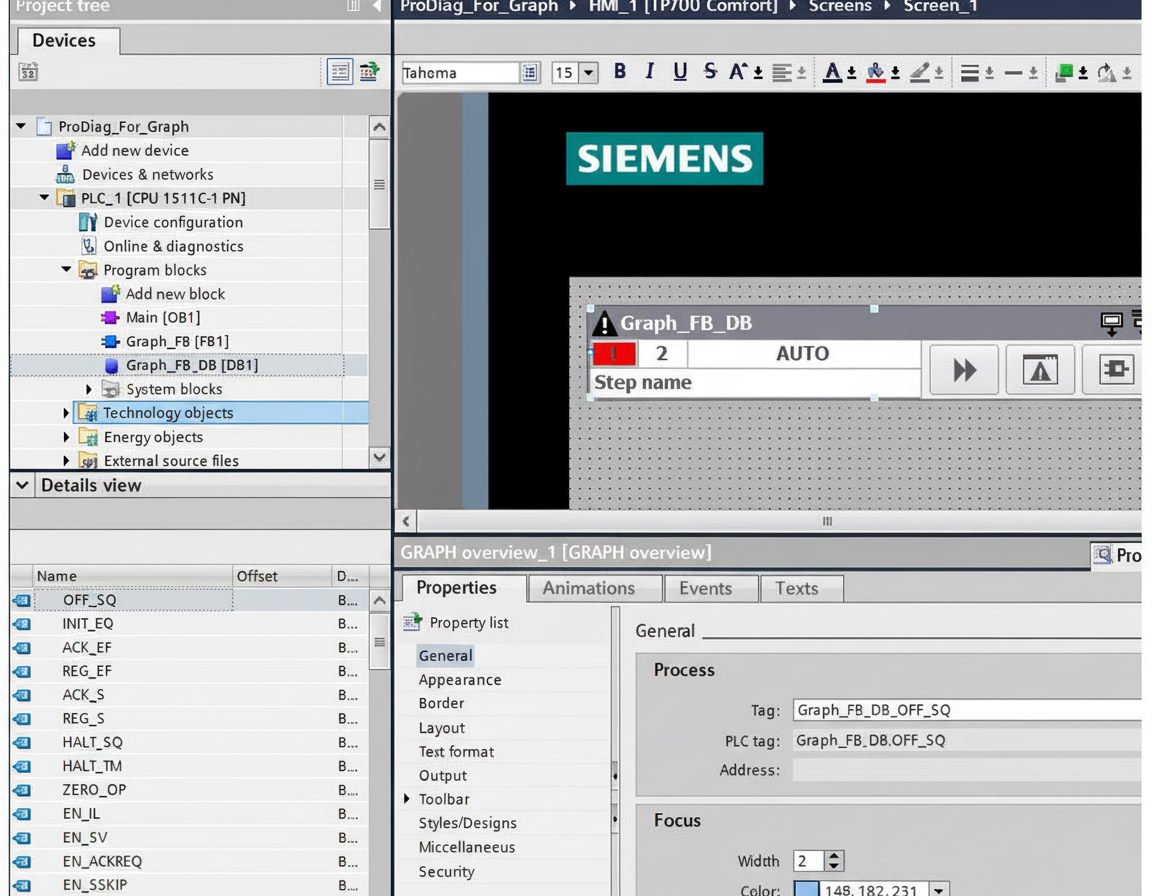
2. On the screen configuration page, add a Graph control. In its properties, bind the variable "SQ_OFF" from the Graph background data block that should be displayed.
3. Create a new screen named "Screen_2". Add a "PLC Code View" control and a button to return to "Screen_1".
4. Create "Screen_3". Add an Alarm control and a button to return to "Screen_1". Set the Alarm control properties to full display.
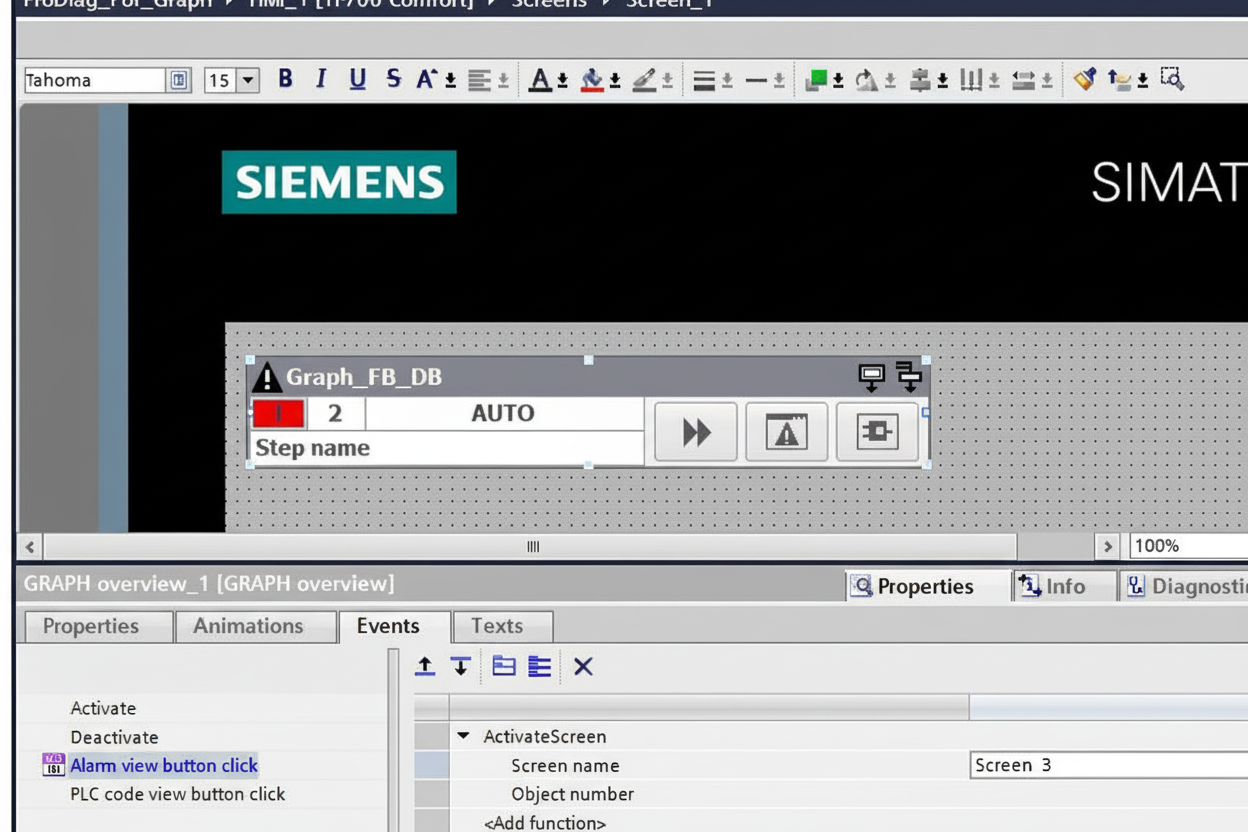
5. Return to "Screen_1" and edit the "Graph overview" control to configure two buttons. Set the "Alarm view button click" to open "Screen_3".
6. Set the "PLC Code view button click" to open "Screen_2".
After opening the HMI simulation, you can observe the Graph status. Graph step 1 is running; red indicates an error.
Click the Alarm button to view the error messages.
Return to the main screen and click the Code View button to see the interlock conditions that caused the Graph error.