Introduction
Motion control and robots require a deep understanding of motors and all components and mechanisms in robotic systems for effective troubleshooting and maintenance. Motion control involves using motors to position actuators and execute precise movements. Although motion control is not always closed-loop, it differs from motor control, whose main objective is to achieve and verify a known position or motion.
01 Stepper Motor Principles and Maintenance
Stepper motors are brushless DC machines whose stator consists of multiple electromagnets arranged around a gear-toothed rotor. Ring-shaped magnets are divided into groups called phases. When a phase is energized, the motor "steps" to the next position.
Microcontroller-based stepper drivers activate driver transistors in the correct sequence. Typical stepper resolution is 200 steps per revolution, but with microstepping drivers this can reach 1600 steps per revolution. Stepper drivers are sometimes called "choppers."
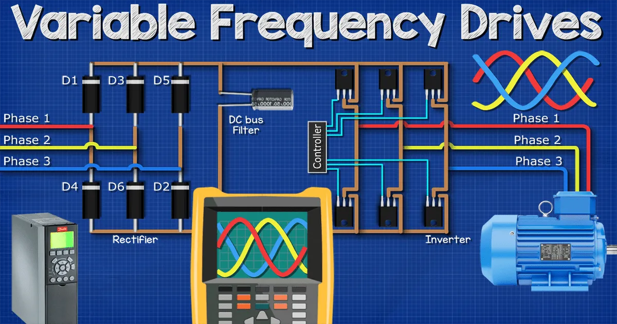
Steppers commonly operate without feedback devices such as encoders or resolvers, making them a lower-cost positioning method than servos, but with limited holding torque. In addition to motor and driver, a pulse generator is required. This can be built into the driver and communicate with a main controller, or pulses can be sent by controllers such as a programmable logic controller (PLC). Troubleshooting a stepper system can include checking voltages and communications in the control circuitry and using an oscilloscope to inspect pulse signals.
02 Servo System Components and Maintenance
A servo or servomechanism uses feedback to control position and torque. Servos can be electric, hydraulic, or pneumatic, though most servos used in industrial automation are motor-driven.
Servo motors may be brushed DC permanent-magnet, brushless permanent-magnet AC, or AC induction machines. They typically include an encoder or resolver and are often integrated with gearheads. Motor assemblies usually have two cable connectors to separate encoder or sensor feedback wiring from motor power.
Servo drives accept encoder inputs and monitor current to measure torque. Temperature sensors and brake control signals are sometimes included in control cables. Servo drives are generally more complex than variable frequency drives and often include logic functions. Modern controllers almost always provide high-speed communication ports to connect with other controllers for coordinated motion, typically using Ethernet-based protocols or sometimes fiber optics.
Servo control algorithms are based on PID position or torque control. Motors must be tuned to match motor and load characteristics to achieve optimal performance. For this reason, motors and drives from the same manufacturer are often sold and used together. Some motors include integrated drives and controllers. These "integrated servos" can be networked to perform complex tasks or used as standalone positioners.
An important distinction between servos and typical AC induction motors controlled by variable frequency drives is that servos provide holding torque at zero speed. If the motor shaft deviates from its commanded position while powered, the motor will attempt to self-correct; failure to reach the preset position may generate a controller fault.
Coordinated motion typically uses a master controller or position to adjust the speed of other controllers. The movement of one axis depends on the changes in another axis or a virtual axis. Fast communication networks dedicated to motion systems are important. Dedicated motion controllers can coordinate servo axes. Machine vision can guide an end effector to the correct location. Motion controllers can be integrated into a PLC rack or used as standalone systems. Many provide separate I/O modules and can be programmed with IEC 61131 PLC languages.
Troubleshooting servo systems often requires familiarity with platform software in addition to standard electrical diagnostics. Drives and controllers usually include built-in diagnostics to detect motor and load issues. Mechanical components such as couplings can also fail.
03 Path Awareness in Robot Motion Control
Industrial robots are used for manufacturing and material handling tasks. Their physical configuration depends on the required functions. Payload and speed requirements help determine the robot type for a given application.
Robots may have up to six or seven motion axes, or as few as three. Two motion axes are required to reach any point in the X-Y plane; three are required to reach any point in X-Y-Z space. To fully control the orientation of a tool at the arm end, three additional axes are needed: pitch, roll, and yaw.
Figure 3 illustrates the six axes needed to reach any point and orientation in three-dimensional space, though robots use different coordinate systems and joint configurations. Origins and axis directions vary by brand and are usually adjustable in software.
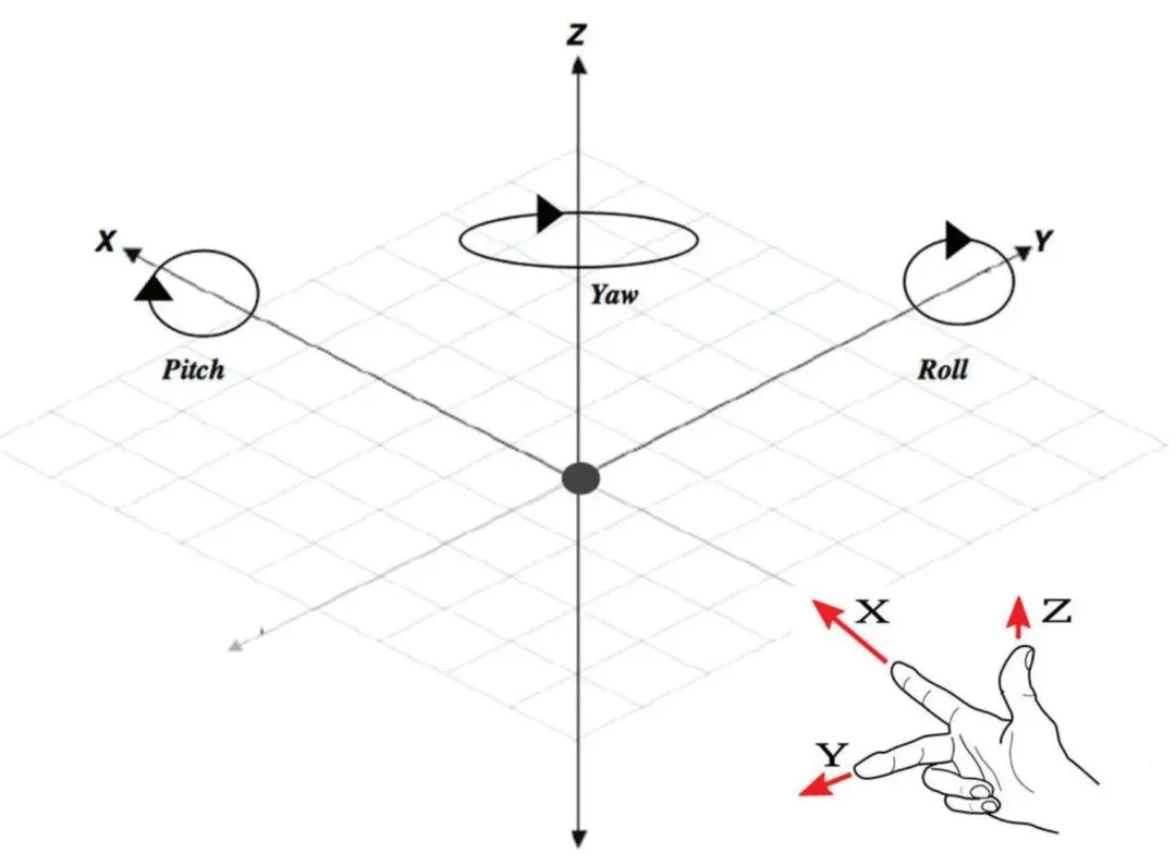
Robot coordinate axes and the right-hand rule.
X, Y, and Z positions are Cartesian coordinates but can be defined from different reference points. When defined from the robot base or an environmental reference, they are called world coordinates, where the origin is fixed. Addressing from the actuator perspective uses tool coordinates, where the origin moves with the end effector and may include offsets from the tool connection to the contact point. Local coordinates can be defined with the origin set within a work area, allowing reference points to be replicated for fixtures or trays.
Individual joints can be independently controlled and are usually defined in degrees. Distances are typically metric (mm) but can be scaled to user-defined units in software. Besides X, Y, and Z, roll, pitch, and yaw may be labeled with other letters like U, V, and W.
The area a robot can reach is called its workspace. Planes and volumes can be defined within a cell to prevent collisions or ensure safety, and safety devices such as light curtains are often integrated into the robot work unit.
Robot controllers continuously calculate the robot position relative to reference points and planned paths. Axes must work together when moving along a defined path, so robots are an advanced example of coordinated motion control. Controllers are typically designed to achieve and maintain position.
Singularities are an important issue in robot motion. A singularity occurs when physical or mathematical constraints prevent the end effector from moving along a specific path. The robot may reach a configuration where it cannot rotate the tool around a certain point, sometimes called gimbal lock. In some configurations, moving a joint in certain directions can damage cables or hoses, so care is required when moving a robot near singularities or when rotating joints to extreme positions. Multiple joint configurations can achieve the same tool position and orientation; this is known as redundant degrees of freedom.
Robot controllers usually perform logic functions and operate external devices, but they are often integrated into a work cell and connected to a master controller such as a PLC. Controllers may be connected to the robot unit via power and signal cables or be built into the robot base. Connections can be 24 V DC power, communication links, or "through" ports and connectors routed internally to the end effector. Through ports often include pneumatic hose connections. Robots are classified by their physical configuration. Examples include articulated six-axis arms for heavy payloads, four-axis SCARA for oriented pick-and-place, and delta configurations for high-speed placements in electronics. Collaborative robots are designed to work directly with humans in shared spaces and have different design considerations.
04 Making Robot Programming Easier
Robots can be programmed from a computer or with a teach pendant. Two types of data must be programmed: programs and position data. To move from one position to another, the robot end effector needs start and end points and a program that defines how to move between them. This may require additional positions and external signals to indicate object presence or motion start.
Positions can be defined in software lists, but a teach pendant simplifies the process. A teach pendant allows an operator to move individual axes and "drive" the robot to desired positions, typically at low speed for accuracy and safety. Many pendants include a three-position deadman switch; a spring-loaded switch must be held in the middle position to enable movement. If it is fully pressed or released, the robot will not move.
Programs are sequences of moves between positions. They can be triggered individually or linked. Robot programming languages vary and are often proprietary, commonly resembling BASIC or assembly-like languages with JUMP and MOVE commands. High-level scripting languages can build data structures or implement mathematical algorithms to compute paths or positions. Some languages support parallel processing, allowing simultaneous actions, for example computing a motion vector while a camera tracks a moving object.
Position tables and program memory are stored separately so one can be changed without affecting the other. This allows positions to be edited via computer or teach pendant to modify or fine-tune paths. Positions are usually defined in world coordinates, but the joint values for a six-axis robot may differ for the same tool pose. Teaching can be done by driving the robot to specific joint configurations and selecting "teach" or by using guided techniques that allow the operator to manually push relaxed joints to a series of positions to describe a path.
05 Troubleshooting and Maintenance Considerations for Robots
Robot troubleshooting and maintenance include using software or the teach pendant to fine-tune positions, replacing end-effector tools, and maintaining electrical or pneumatic connections. Like motion controllers and drives, robot controllers report faults and diagnostic data. Most faults stop robot motion and may require the operator to move the robot to a safe position after correcting the issue.
Robot work cells typically interface with PLCs and HMIs. The PLC communicates with the robot and displays fault codes and other data on the HMI. Because this involves two communication links (robot-PLC and PLC-HMI), verifying both are functioning is important.
End effector connections may use M8 or M12 cable connectors, junction boxes with terminals, ASI (Actuator Sensor Interface), or Ethernet remote I/O. Knowing the type of communication interface can help when inspecting tools or fixtures. Check documentation or inspect the fixture area to locate these connections.
Different colored lines in system diagrams indicate that connections between components can include discrete wiring, communications, pneumatics, or combinations of power and feedback wiring for the robot-controller connection. This complexity makes troubleshooting challenging because it spans mechanical, electrical, and control disciplines.
Systems often include actuators not controlled by the robot controller, for example workpiece clamps. These require handshake signals between the PLC and the robot controller. External systems for material handling and conveyors can interface to the PLC, and multiple robots may be present. Preventing collisions between multiple robots and tools can be complex. Safety devices such as light curtains, floor scanners, and door switches can interface with the robot controller and PLC. Machine vision can be used to locate parts, adding another layer of system complexity.