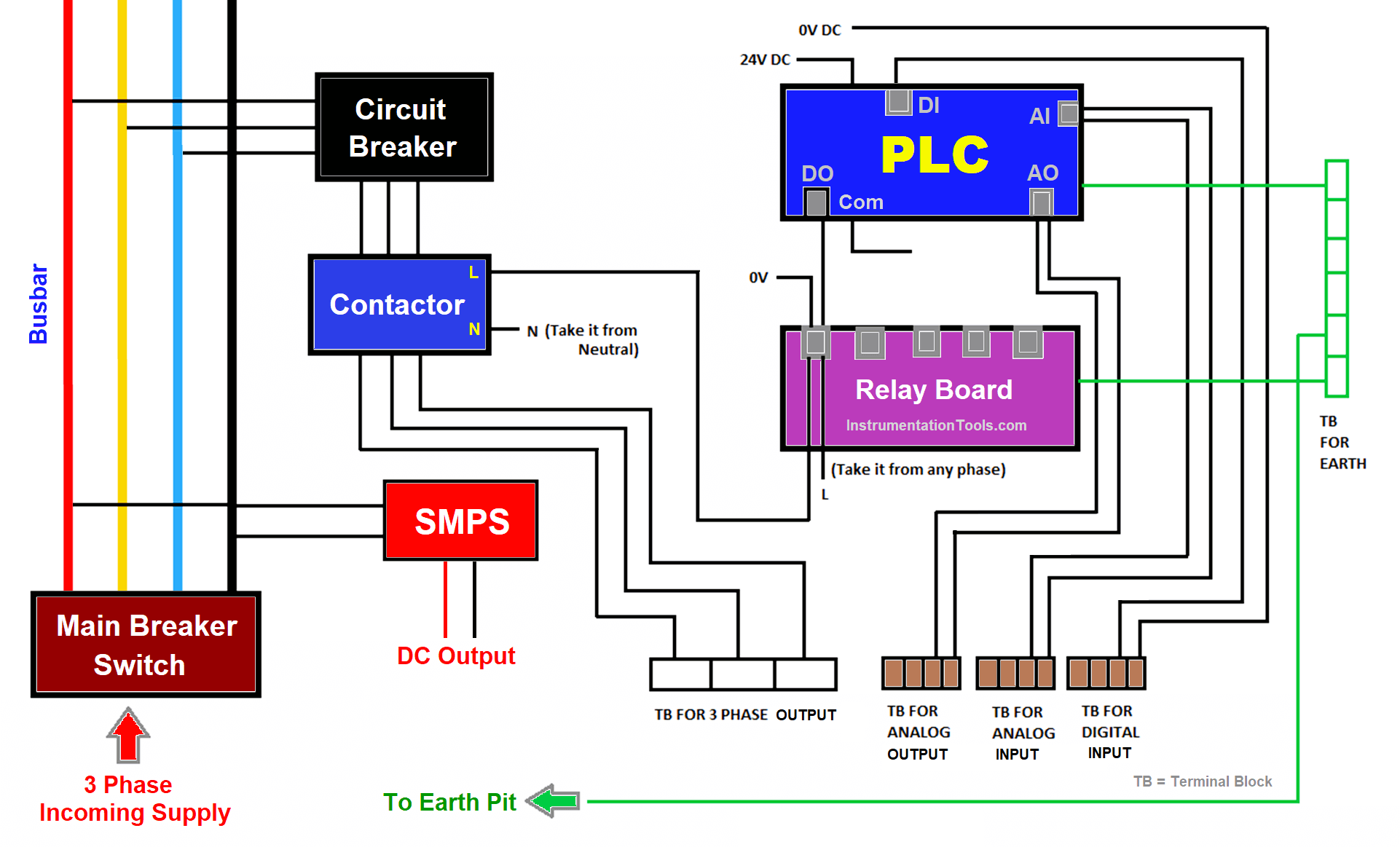
Introduction to PLC Positioning and Servo Control Systems
PLC controls servo drives by sending drive pulses. Speed is controlled by pulse frequency, and travel distance is controlled by pulse count. The servo driver is the actuator: it receives signals from the PLC to control the motor and uses a position encoder for precise positioning.
1. Basic Positioning Unit
A single FX3U CPU can drive three servo axes. The PLC pulse output terminals are fixed at Y0, Y1, and Y2; whether a given module supports pulse output should be checked in its manual. The remaining outputs serve as direction outputs. Maximum pulse frequency is 100 kHz.
2. FX3U PLC Special Adapter Expansion Unit
If the base unit's pulse output Y does not function, use the special adapter expansion unit so that the Y input of the adapter outputs pulses.
3. PLC Output Internal Circuit
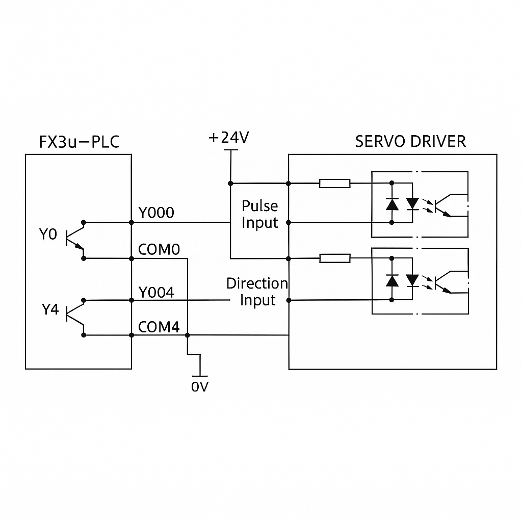
Y0 provides pulse frequency and pulse count, while Y4 is used for direction output. These are controlled by positioning instructions, so separate programming of Y4 is not required.
FX3U-PLC Positioning Control Instructions
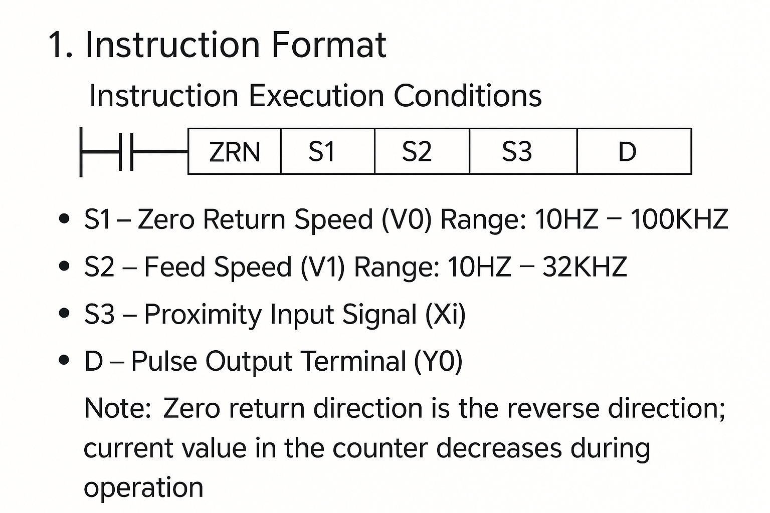
Homing Command: ZRN
The homing (origin return) command ZRN first moves at speed S1. When it reaches the near point, it switches to crawling speed S2. D is used as an output. ZRN can only be used when approaching the origin from the positive direction; it cannot be used when moving in the negative direction.
Speed Change and Zeroing Signal During ZRN
1) Zero signal selection for the Y0 pulse output (option 1)
- M8341 = ON: zeroing signal enabled
- M8464 = OFF: zeroing output terminal fixed enabled
- Y4: fixed zero output terminal
2) Zero signal selection for the Y0 pulse output (option 2)
- M8341 = ON: zeroing signal enabled
- M8464 = ON: zeroing output specified as enabled
- D8464: register specifying zero output
In the above diagram, when execution conditions are met, set M8341 = 1 and M8464 = 1, mapping Y20 to D8464.
Note: If H0028 is set, it corresponds to Y028; if Y028 does not exist, a calculation error will occur.
3) Fixed zero output terminal (consistent with pulse output terminal)
4) Specified zero output terminal (arbitrary selection)
Maximum Speed Setting for Positioning Instructions
The maximum speed limits the highest pulse frequency output by the PLC and is the upper frequency limit for positioning commands.
The output is 32-bit and thus uses two registers.
Base Speed (Minimum Speed) Setting for Positioning
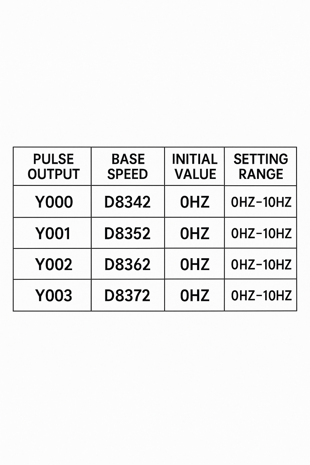
For servo motors, set base speed = 0 Hz. For stepper motors, set base speed ≠ 0 Hz to avoid losing steps.
Acceleration Time Setting for Positioning
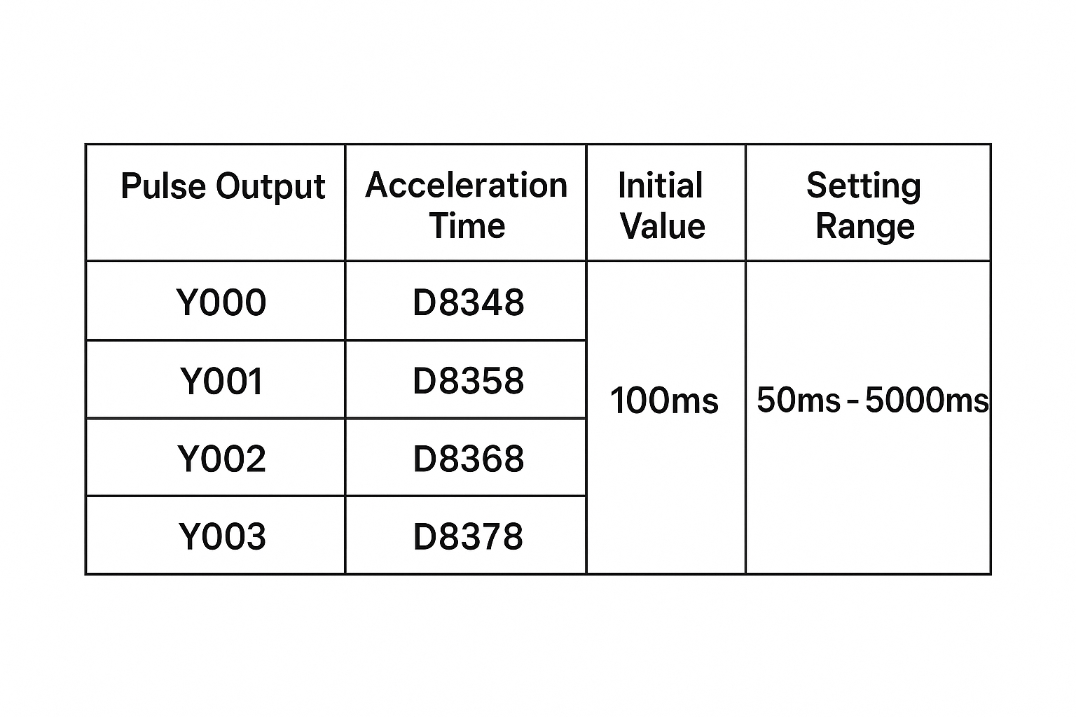
Acceleration time is the time required to accelerate from base speed to maximum speed. Set it appropriately to avoid motor shock.
Deceleration Time Setting for Positioning
Positioning Instruction Flags (Corresponding to Y0 Pulse Output Flags)
Flags indicate the execution status of positioning commands.
1) M8340: Pulse output monitoring flag
M8340 = ON when Y0 outputs pulses. M8340 = OFF when Y0 stops outputting pulses.
2) M8348: Positioning instruction driving flag
M8348 = ON when the instruction input is triggered. If the input condition remains true, M8348 stays ON even after instruction execution finishes. M8348 is OFF only when the instruction input is turned off.
3) M8349: Pulse stop flag
Indicates Y0 pulse output stop. When M8349 = ON, Y0 pulse output stops immediately. To resume pulses, set M8349 = OFF and toggle the instruction input from OFF to ON to restart.
Use case: In an emergency stop, set M8349 = ON to immediately stop pulse output and halt the motor. This is a PLC-side emergency stop; it is recommended that the emergency stop button also be wired to the servo drive side for safety.
4) M8029: Normal completion flag for positioning instructions
This is a shared flag for positioning instructions. When a positioning instruction completes normally, M8029 outputs a pulse one scan cycle long.
5) M8329: Abnormal completion flag for positioning instructions
This is also a shared flag. If the moving table encounters a limit switch or another abnormal stop, the motor decelerates and stops. M8329 outputs a pulse one scan cycle long and the instruction terminates.
6) Current value registers: D8341, D8340
D8341 and D8340 store the current position of the table relative to the origin in real time. When the positioning instruction outputs forward pulses, the current value increases; when it outputs reverse pulses, the current value decreases. If the PLC loses power, the current registers are cleared, so after power-up the mechanical table must be returned to the origin by executing a homing command.
If the PLC uses battery backup for registers, execute the homing command once at the start to synchronize positions.
Limit Switches for Forward and Reverse Travel
Two sets of limit switches are recommended for protection: Limit set 1 wired to the PLC and limit set 2 wired to the servo drive. When the limit flag is ON, the motor decelerates and stops.
Y0: M8343, M8344: when the limit flag is ON, the motor decelerates and stops.
Y1: M8353, M8354
Y2: M8363, M8364
Y3: M8373, M8374
Y0 near-point signal can be logic-inverted:
- M8345 = OFF: positive logic, signal valid when ON
- M8345 = ON: negative logic, signal valid when OFF
Homing with DOG Search: DSZR
The zero input signal uses the Z-phase pulse from the encoder; the encoder generates one Z pulse per motor revolution. To align the mechanical origin with the electrical origin, use DOG search.
When the X near-point signal is received, the axis slows to creeping speed and enters the DOG zone. When the Z (index) pulse is detected within the DOG zone, movement stops.