1. Construction Process
The construction process for a large LED information display system is as follows: LED installation crew arrival - on-site confirmation of installation locations - determine final suitable dimensions based on site orientation - conduit and cable routing pre-embed (data cable comprehensive wiring points reserved with interface provisions and power interface provisions for mains) - screen module fabrication - screen installation (in coordination with interior finishes) - screen commissioning - count and record bright/dark pixel defects - system acceptance - LED display system training - system handover.
2. Pre-construction Preparations
During installation of the display and touchscreen systems, each screen must closely coordinate with building works to complete the required conduit and piping pre-embed work. Ensure routing does not cross or interfere with mains power or HVAC conduits. Also ensure the subsequent screen installation will not compromise the finished interior appearance and that the final installation contributes to the building aesthetics and modern information presentation.
Because interior finishing directly affects screen installation, the owner should coordinate the schedule so that finishing works and screen installation proceed in sync.
Throughout construction there are coordination relationships with other contractors and unforeseeable factors. When incidents occur, the owner or project supervisor should coordinate all parties according to the actual situation.
3. Key Construction Points and Considerations
All information interfaces for the large-screen information system use standard network RJ45 ports for connectivity. For a municipal project involving LEDs & Lighting infrastructure, such as a large-scale LED screen, the network topology generally follows one of two approaches:
- Network via pre-reserved comprehensive wiring points. This method places fewer demands on conduit pre-embed work as long as the comprehensive cabling system is reserved according to the LED installation locations.
- Network via an internal subnet rather than building comprehensive wiring points. In this case the screen system can transmit signals over fiber, then perform optical-to-electrical conversion at the screen after installation to realize the data stream.
The display system also requires local mains power. During conduit pre-embed stage, coordinate requirements with the mains power specialist, since cross-discipline handoffs often create small but important issues during installation.
4. Conduit and Cabling Works
Coordinate closely with structural trades and promptly seal conduit openings to prevent debris from entering and blocking conduits.
For lengthy conduits or runs with many bends, pre-thread steel wire to facilitate later cable-pulling.
Where conduits or conduit-to-box connections occur, ensure proper grounding. Use threaded connections bridged with steel not less than 6 mm in diameter to ensure robust grounding.
Separate conduits by system type, voltage level, and current class. Before pulling cables, use compressed air to remove water and debris from conduits, and apply a small amount of talc to reduce friction. Inspect conduit edges and remove burrs to prevent damage to conductor insulation during pulling.
Use a cable reel when paying out wire to prevent twisting. Place cable joints inside junction boxes. Fit conduit entry protectors before and after pulling where required. After conductor connections, solder joints where appropriate and wrap securely with insulating tape.
5. Equipment Installation
Installation Sequence Notes
Power Distribution
The display system operates on 220 V AC, with total power consumption equal to the sum of each component's consumption.
Screen power should be supplied with a three-phase five-wire system and an embedded protective earth.
Earth Electrode
Earth resistance should be ≤ 4 Ω. Users should follow local standards, typically using deeply buried copper-clad steel rods and managing soil moisture and salinity to meet equipment grounding requirements.
Goods Inspection and Unpacking
Verify the number of shipped items based on the contracted screen area. On receipt, check quantities against shipping documents, then open crates and inspect contents per the packing list.
Screen Installation
Power distribution installation: the display uses 220 V AC three-phase five-wire supply.
Module Board (Cabinet) Assembly Steps
- Verify the frame and support brackets are secure.
- Install display panels from the bottom upward, layer by layer.
- Connect inter-module (cabinet) cables.
- Connect power cables.
Driver Software Installation
The driver software is compatible with Windows 2000 and Windows XP platforms; its installation procedure is the same as other device drivers.
Earth Conductor Connections
Connect all local grounding points to the main earth electrode.
System Connection Precautions
- Observe connector polarity and orientation.
- Ensure all connectors are fully seated and secure.
- Ensure protective earth is properly connected.
6. System Commissioning
Before factory acceptance each screen has passed quality inspections and finished-screen tests, so after installation commissioning focuses on overall brightness adjustment and software network-controlled display tuning. Brightness testing is visual and performed on site by the parties involved. Networked software control and screen display are the main commissioning priorities, described below.
1) Multimedia Content Editing and Tuning
Text: The most common content type. Preparation and processing are straightforward: text composition, translation (for multi-language systems), data entry, and text effects. Software tools allow selection of fonts, sizes, colors, alignments, and special effects for subsequent screen-based adjustment and proofreading.
Graphics: Graphics can convey large amounts of information intuitively and are essential for creating attractive interfaces. In the production tools, focus on testing support for graphic scaling, cropping, and stitching.
2) Display Monitoring and Control
The display is the system's key device. The host control computer should provide full control over displayed content and display modes, while control software should offer interfaces to monitor device operating status.
3) Network Function Testing
Computer devices form a LAN to share internal resources. Standard network interfaces ensure standard network connectivity, and network software provides information distribution and network control. After forming the network, verify that each terminal responds promptly to control commands and prepare a commissioning acceptance report.
Related Reading: Fixing LED Flicker, Failure to Light, and Dimming
7. Common Commissioning Faults and Solutions
(1) Entire screen not lit
Verify the host computer is operating properly. Check the connection and contact condition of cables between the host and the display control system. Confirm the control system has power and that its output cables are connected in the correct order.
If the above are correct, inspect the screen: confirm the screen has power and that the screen power supply is functioning. Verify control-system-to-screen data cables are correctly connected. Check whether ambient temperature and humidity exceed the product's specified operating limits.
(2) Image unstable, horizontal shaking
This is caused by a potential difference between the control system digital ground and the screen digital ground. Check that the control system output ground and the input ground of the first module board are properly connected.
(3) Image position incorrect or no image visible because content is outside the mapped area
- Check the frame offset settings and adjust to appropriate values.
- Verify the frame position matches the intended playback area and adjust if necessary.
- Check the controller communication cable connection and reconnect correctly if needed.
(4) Screen carrying static charge
Immediately turn off screen power and check that the power cable protective earth is properly connected.
Use a multimeter to measure resistance between screen metal parts and earth to confirm the chassis earthing is good.
(5) Missing color channels in the image
- The corresponding power supply channel may be in protection mode or experiencing output failure.
- The color brightness setting may be at minimum.
- Data connections may be loose.
- The corresponding data channel may be faulty.
(6) Screen image has a background tint
External interference exceeds system tolerance. Refresh the image.
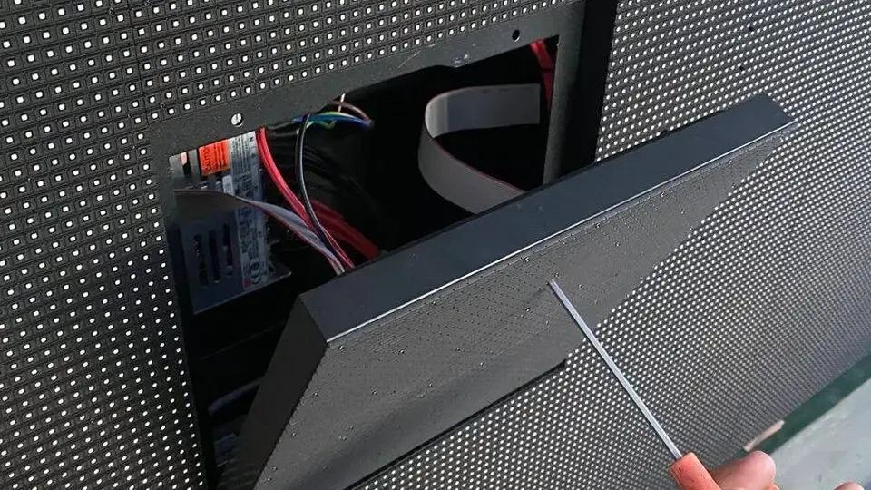
(7) Localized module or two modules display abnormally or are dark
Open the rear access and check whether the power supply feeding the two affected module boards is functioning. If not, replace with a correct working power supply. Check data cables for proper seating; reseat or replace if defective.
8. Trial Operation and Testing
Power-up and Initial Tests
After system assembly, check all signal and data cable connections, then power the display. Use a dedicated tester to inspect the screen at 16-row intervals. When full-screen checks are complete and no issues are found, power down all supplies. Restore normal connections, remove the tester, and restart the system following the controller-to-screen power-up sequence.
Trial Operation
Each module board undergoes aging, temperature, and vibration tests before leaving the factory. Once assembled correctly, the system can operate reliably for extended periods. Normal operating environmental conditions are: AC supply voltage 220 V, 50/60 Hz; operating temperature range -20°C to +60°C; relative humidity 10% to 95%.