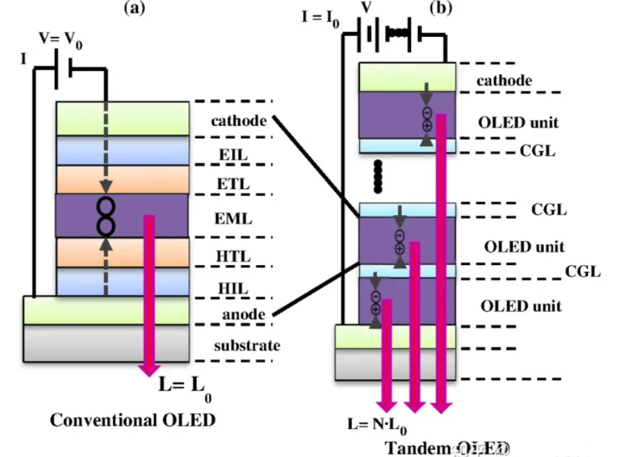
Circuit diagram
This circuit shows how to use an LED as a night light. The same principle can be applied to drive larger, brighter lamps.
Required components
- 9V battery
- Breadboard
- Photoresistor (LDR) — about 5 kΩ in bright light, over 200 kΩ in darkness
- Transistor BC547
- Resistor 100 kΩ
- Resistor 470 Ω
- Light-emitting diode (LED)
Connecting the circuit
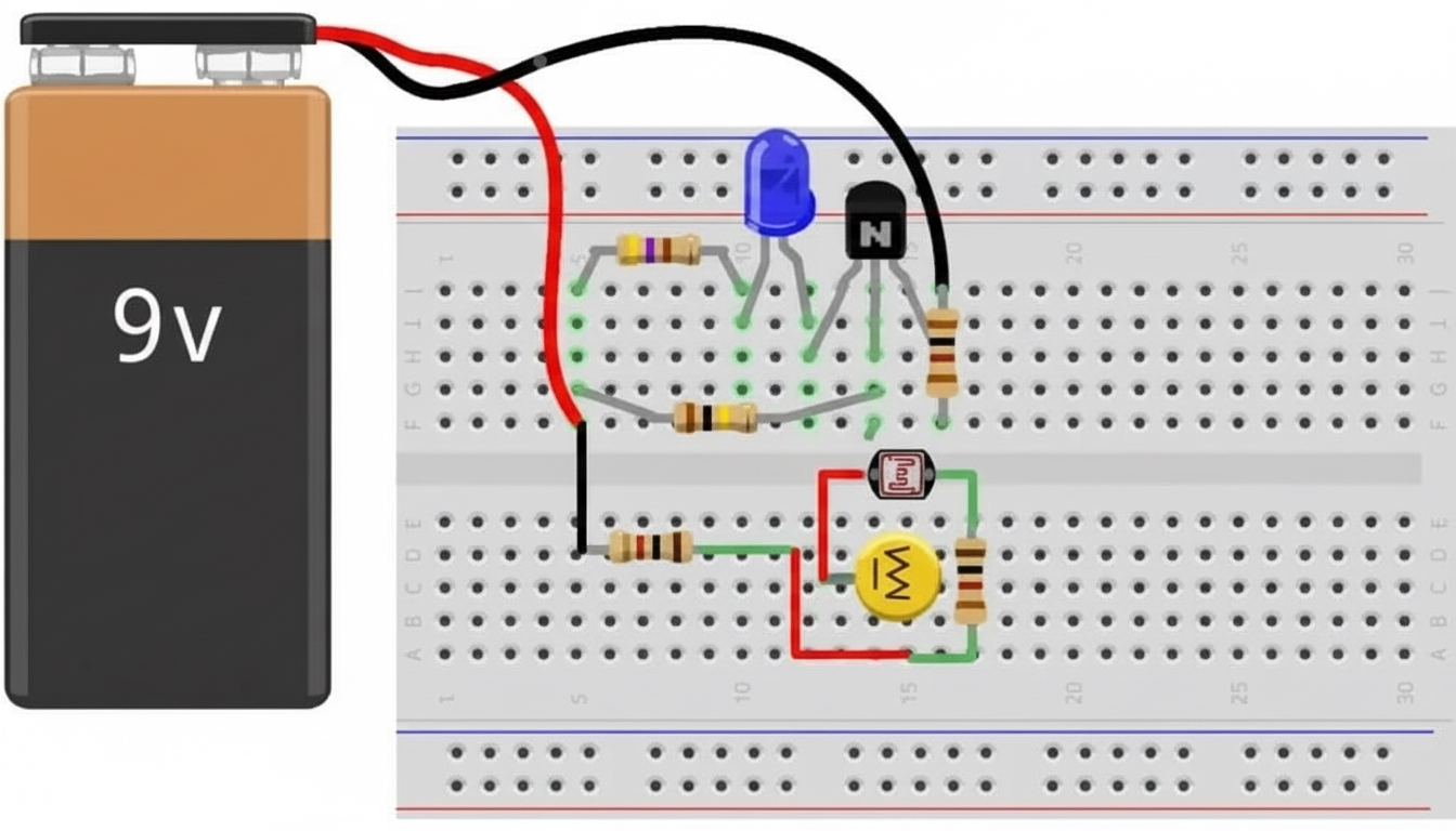
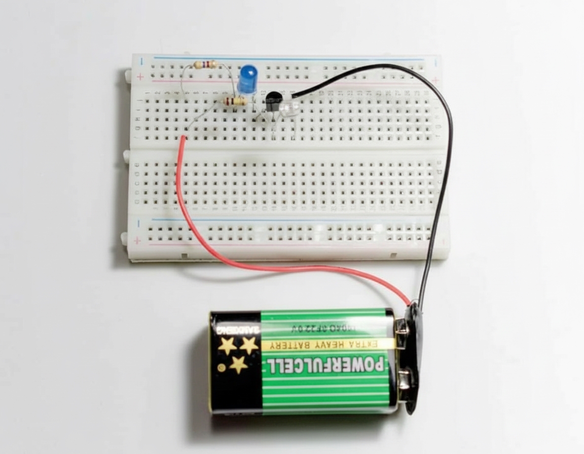
There are many ways to wire this circuit. A breadboard is recommended for quick assembly and easy reuse of components. The image below shows one way to place the components on a breadboard:
Working principle
The photoresistor and the 100 kΩ resistor form a voltage divider. When light is abundant, the photoresistor has low resistance, so the divider output voltage is low. The transistor is off and cuts off current to the LED, so the LED is dark. In darkness, the photoresistor has high resistance, so the divider provides a higher output voltage that turns the transistor on. The LED then receives current and lights up.
Divider output voltage
With ample light and the photoresistor at low resistance, the divider output is about 0.5 V, which is not enough to turn the transistor on. In darkness, the open-circuit divider output is about 4.5 V. However, because the divider output is connected to the transistor base, the voltage is limited by the base-emitter forward voltage, roughly 0.7 V.