Introduction
The American Physical Society highlighted a notable development in 2021 as "playful rotations" in physics, describing a novel spinning top designed by astrophysicist Kenneth Brechet. Brechet's interest in gyroscopes was inspired by his study of neutron star rotation, which can exhibit wobble or precession similar to gyroscopic behavior. He designed a one-way spinning top called DeltaCELT using mathematical constants. The top features two elliptical depressions on its upper surface whose axis ratio equals the Feigenbaum constant. This asymmetric shape gives DeltaCELT a preferred rotation direction: when spun counterclockwise it rotates normally and freely; when spun clockwise it quickly slows, stops, and converts oscillation into counterclockwise rotation. Such behavior may offer conceptual inspiration for mathematical physics and gyroscope design.
Gyroscopes are applied to angular velocity measurement because of their ability to maintain an axis and to precess. According to Newton's first law, an object not subject to external forces tends to preserve its state of motion. A rapidly spinning rotor conserves angular momentum in both magnitude and direction absent external torque, which yields the characteristic of axis stability. When an external torque is applied, angular momentum changes at a rate proportional to the torque and in its direction; the gyroscope's angular momentum vector responds slowly to the applied torque, resulting in precession. The precession angular velocity direction follows the right-hand rule. Instruments that measure angular rate based on these principles are called gyroscopes. The first mechanical gyroscope was developed in 1904 by Hermann Anschütz and Elmer Sperry, enabling precise angular rate measurement. Since then, gyroscope technology has evolved through rotor-based, optical, quantum, and resonant architectures and has seen widespread use in defense, autonomous driving, camera stabilization, gaming, and other applications. The sections below describe several common gyroscope types.
1. Traditional Rotor Gyroscopes
Traditional rotor gyroscopes are the earliest type of gyroscope. They rely on the axis stability and precession of a high-speed rotor to measure the carrier's angular velocity. In operation, the high-speed rotor is mounted inside a frame with one degree of freedom. These gyroscopes are sensitive to external vibration and to friction between the rotor and its support, so the support system is a critical determinant of accuracy. Rotor gyroscopes are classified by their support type: ball-bearing supported, gas-bearing, liquid-bearing, dynamically tuned, electrostatic, and so on. The three-bearing gyroscope is a representative example of this class.
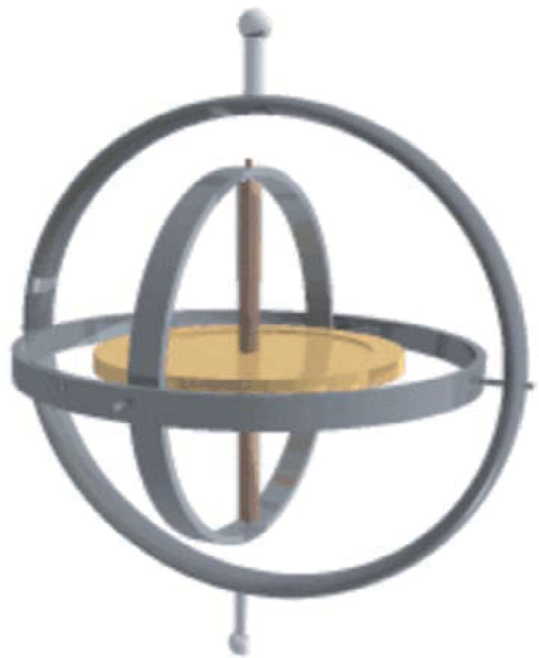
Figure 1: Traditional rotor gyroscope
The three-bearing gyroscope is a single-degree-of-freedom integrating gyroscope whose support system combines liquid bearing, dynamic-pressure gas bearing, and magnetic suspension. Its components include a gyro motor, float assembly, angle sensor, torque motor, magnetic suspension elements, high-density float oil, jewel bearings, temperature control, housing, end caps, and connectors. The motor rotor uses dynamic-pressure gas bearings; the gyro motor uses liquid flotation; magnetic suspension reduces friction between the float assembly and jewel bearings.
In operation the gyro housing is fixed to the mounting base. The gyro motor spins at high speed, creating angular momentum and the gyroscopic effect. When there is angular velocity or torque about the input axis, the gyroscope precesses about the output axis. The gyro motor and frame form a stable angular momentum H about the spin axis. When the base rotates about the input axis, the frame precesses about the output axis and damping torque arises from the float oil. At steady state, the net torque about the output axis is zero; the float angle is a function of the carrier angular velocity ωI. The float angle is measured by sensors to determine ωI.
Traditional rotor gyroscopes currently offer the highest accuracy in engineering applications, but they are large. They are primarily used in strategic systems such as ballistic submarines and missiles that demand very high precision and accommodate larger form factors.
2. Optical Gyroscopes
Optical gyroscopes are based on the Sagnac effect. For a simple ideal circular optical path, if the loop is stationary relative to inertial space, two counterpropagating beams injected at a point travel the same optical path length and return simultaneously. If the loop rotates, the injection point shifts; the counterclockwise beam completes the loop with a path shorter than 2πR while the clockwise beam experiences a longer path. This path difference creates a time difference and thus a phase difference. Since the two beams have equal frequency, the phase difference is constant and produces interference fringes that shift when the loop plane rotates. This fringe shift is the Sagnac effect.
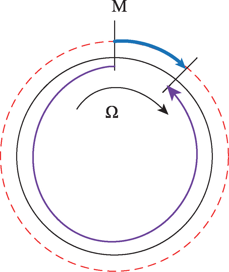
Figure 2: Illustration of the Sagnac effect
Optical gyroscopes include ring laser gyroscopes and fiber optic gyroscopes; both exploit the Sagnac effect. The following summarizes fiber optic gyroscope (FOG) operation.
In 1976, Vali and Shorthill built the first fiber optic gyroscope. Currently, fiber optic gyroscopes in China have reached accuracies of about 0.001°/h. Compared with mechanical gyroscopes, optical gyroscopes offer strong interference immunity, no wear, long lifetime, reliable signals, wider dynamic range, simpler structure, and lower cost.
An interferometric fiber optic gyroscope consists of a light source, modulator, fiber loop (radius R), coupler, and detector. Light from the source is split into two beams that enter the fiber loop from opposite ends and travel in opposite directions. They recombine at the coupler and interfere. If the gyroscope rotates at angular velocity Ω, the Sagnac effect produces a phase difference:
Δφ = [(8nπ2R2/λc)]Ω
where n is the number of fiber turns, λ is the wavelength, and c is the speed of light in vacuum. A phase demodulator extracts Δφ from the interference signal, and Ω is computed from the equation above.
Fiber optic gyroscope technology has matured and its performance approaches that required for high-performance inertial navigation. FOGs are widely integrated in strapdown inertial systems used in aircraft and vehicle navigation, and they are used in civil applications such as oil drilling and robotic control.
3. Vibrating Gyroscopes
Vibrating gyroscopes are based on the Coriolis effect. Major subtypes include hemispherical resonator gyroscopes (HRG) and MEMS gyroscopes.
The hemispherical resonator gyroscope is a solid-wave device that exploits Coriolis-induced motion of standing waves in a hemispherical resonator. It comprises an excitation shell, excitation electrodes, the resonator, sensing electrodes, and a readout base. The resonator is the core component. The gyroscopic effect arises when radial standing waves in the resonator precess under external rotation due to Coriolis forces, producing a change in mode orientation. HRGs provide high accuracy, high reliability, and long life. Their structure is simple and robust; current HRG accuracy can reach about 0.0001°/h, achieving inertial-grade performance; HRGs have been used on the Hubble Space Telescope.
HRG components such as the excitation shell, resonator, and readout base are fabricated from fused silica, a material with stable physical and chemical properties and a high quality factor. The HRG is structurally simple and, once assembled, can be rigidly fixed, yielding high shock resistance. During excitation, resonator amplitudes are only a few micrometers, avoiding internal damage or stress concentration. In the second-order standing wave state, four antinodes and nodes form. Without external rotation, their positions are fixed. When an external angular velocity is present, Coriolis acceleration alters the vibration pattern by adding a tangential force component to radial driving forces, causing the standing wave pattern to precess. The precession angle is proportional to the applied rotation and depends on the resonator material properties, not on rotation magnitude.
HRGs operate in two modes: force-balance and whole-angle. In force-balance mode (a rate gyroscope), feedback forces counteract Coriolis forces so the standing wave pattern remains aligned with the housing; the feedback magnitude produces an output voltage proportional to angular rate. In whole-angle mode (an integrating gyroscope), the standing wave freely precesses with external angular velocity; detecting the standing wave orientation yields a direct measure of accumulated angle.
HRGs are promising for achieving high accuracy with reduced size and cost and have attracted attention in inertial technology fields worldwide.
MEMS gyroscopes are another branch of vibrating gyroscopes. MEMS devices are compact, lightweight, low-power, and low-cost, and are widely used in military and civilian applications. MEMS gyroscopes rely on the Coriolis effect: when a mass element vibrates sinusoidally in a plane that is rotating, Coriolis acceleration induces motion perpendicular to the plane (the sense axis) with amplitude proportional to angular velocity. MEMS gyroscopes convert rotation into measurable transverse vibration and sense displacement to determine input angular rate. Different MEMS architectures detect Coriolis forces in different ways.
MEMS gyroscopes are highly integrated and suitable for mass production. They are widely used in digital cameras, automobiles, robots, smartphones, and many consumer products, representing a major trend in gyroscope miniaturization. However, MEMS gyroscopes have lower accuracy and are mainly used in tactical military and civilian markets. Current research focuses on further miniaturization, fabrication improvements, and circuit-level error compensation.
4. Quantum Gyroscopes
Advances in quantum technology have enabled the development of quantum gyroscopes, which aim to measure angular velocity with very high sensitivity based on quantum principles. Quantum gyroscopes include atom interferometer gyroscopes and atomic spin gyroscopes. Quantum gyroscope technology is still largely at the experimental stage and has not yet been widely deployed.
Atom interferometer gyroscopes operate on wave interference analogous to optical interferometers but exploit the wave nature of atoms. Atomic de Broglie wavelengths are much shorter than optical wavelengths (on the order of 0.01 nm at room temperature compared with 400–700 nm for visible light), enabling higher resolution. Leading development focuses on cold-atom interferometer gyroscopes.
Cold-atom interferometers use magneto-optical traps to cool and confine atoms near the trap center, increasing interaction time for matter-wave interference. Laser beams then guide atomic ensembles along defined paths. When atoms are prepared in the same internal state and velocity, interference occurs. State-selection techniques remove magnetically sensitive atoms and select velocities, improving coherence. For the same interferometer area, atom interferometers produce phase shifts roughly ten orders of magnitude larger than light-based gyroscopes, offering much higher sensitivity.
Atomic spin gyroscopes include nuclear magnetic resonance gyroscopes (NMRG), spin-exchange relaxation-free gyroscopes (SERFG), and diamond NV-center gyroscopes. NMRGs sense carrier rotation via nuclear spin, SERFGs via electron spin, and NV-center gyroscopes via electron spin in diamond vacancies. The following summarizes SERFG operation.
SERFGs are solid-state gyroscopes where angular momentum arises from interactions between alkali-metal atoms in a vapor cell and noble gas nuclei. The core elements are the alkali atom electron spins and the noble gas nuclear spins. Alkali atoms can be treated as possessing a single valence electron, and noble gas total angular momentum is dominated by nuclear spin.
Atomic spin gyroscopes typically include a pump laser, an alkali vapor cell, magnetic shielding, and a probe laser. In equilibrium, electronic and nuclear spins are randomly oriented. Under applied optical and magnetic fields, electron spins become polarized and collisionally transfer polarization to nuclei. To maintain a stable reference axis, external magnetic fields must be shielded. When the assembly is rotated with the carrier, the pump laser (locked to the rotating body) polarizes and orients spins along the pump direction. The spins precess slightly away from their initial orientation in response to rotation. The probe laser, also rotating with the body, detects the spin orientation through changes in optical polarization. Differences between electron and nuclear orientations alter the probe beam polarization, which is related to the spin angle deviation and thus to angular velocity.
Figure 8: Atomic spin gyroscope schematic
Atomic gyroscopes remain in the prototype stage and are not yet in widespread practical use, but the technology is maturing and may significantly improve inertial navigation sensitivity when engineered for deployment.
5. Conclusion
Different gyroscope types differ in principle, structure, accuracy, and cost. Advances in physics, electronics, and computing continue to drive improvements in gyroscope precision, size, and reliability to meet military and civilian needs. Novel devices such as the unidirectional DeltaCELT top may offer new design ideas, and the use of mathematical constants like the Feigenbaum constant in gyroscope geometry suggests additional avenues for innovation. As gyroscope technology evolves, engineers will find new ways to apply these devices in navigation and other fields.