Introduction
A common saying goes: "A thin sheet of paper is easily torn." Aerodynamic design for aircraft often encounters technical challenges. From an aerodynamics perspective, and based on years of design, testing, and simulation experience, this article summarizes practical insights for discussion among engineers and experts.
Fan is a simulation instructor with a master's degree in fluid mechanics from Northwestern Polytechnical University and is a senior engineer. He has nine years of experience in aircraft aerodynamic layout design and four years in launch vehicle aerothermodynamics, with expertise in aerodynamic simulation, layout design, and unsteady flow.
Changes in Aerodynamic Layout Design Process
Traditional design work, after defining aircraft requirements, relied on engineering experience to propose multiple aerodynamic shapes whose dimensions stayed within practical engineering constraints. These designs incorporated shape constraints and used engineering algorithms for parametric design. Once preliminary schemes appeared feasible, wind tunnel testing was introduced into the process.
For complex-shaped aircraft that must control costs, it is important to determine likely product performance early. This requires high-fidelity geometric models and CFD simulation as early as possible in the design cycle.
Case Studies in Aerodynamic Design
1. The Su-27: Aerodynamic Innovations
The development that led to the Su-27 was long and difficult, but the result showed that pursuing new ideas and integrating them into a practical design was correct. The T-10 prototype exhibited several shortcomings, but the overall concept appeared promising. This led to a complex development and testing phase involving at least ten prototypes.
To address T-10 issues, the aircraft underwent a comprehensive redesign. The fully revised T-10S made its maiden flight on April 20, 1981.
The evolution of the Su-27 layout shows a mindset of incorporating potentially new technologies, rapidly optimizing layouts, and using multiple prototype flights to reveal problems and refine the design. Contemporary programs such as SpaceX follow a similar iterative approach.
2. Aerodynamic Layouts for Recoverable Rockets with Stage Return
Unlike Falcon 9 booster recovery, stage recovery for heavy launch vehicles must also meet range requirements. The aerodynamic layout of a replica "New Glenn" and that of a heavy launch vehicle are analyzed below, followed by a discussion of current grid fin designs.
Figures show that when the center of mass is at positions G4 and later, a trim angle exists at supersonic speed. For example, at position G3, comparing 0° and 20° yields a drag increase of 51%. For G3 at 0° and 30°, the drag increase is 140%.
From data on boattail-less configurations, the role of boattails can be summarized:
(1) For boattail-less bodies that have a trim angle, adding a boattail increases the trim angle of the body.
(2) For boattail-less bodies that do not have a trim angle, adding a boattail can produce a positive trim angle.
Figure 1 Replica "New Glenn" external shape
Designing modern grid fins
First determine the loads acting on the grid fin; overall layout constraints typically fix the geometric dimensions.
Figure 2 Primary grid fin forms: framed, upright honeycomb, and tilted honeycomb
When the number of grid cells n is fixed, linear relations among geometric parameters can be obtained. Because certain values are constant, a relation of 1.414n arises. For some n values, these relations are shown in Figure 3.
Rounding the windward edges can substantially reduce heat flux density, by up to 50%.
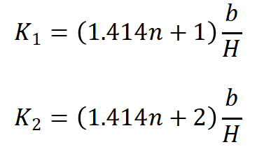
Figure 3 Grid fin parameter relationships
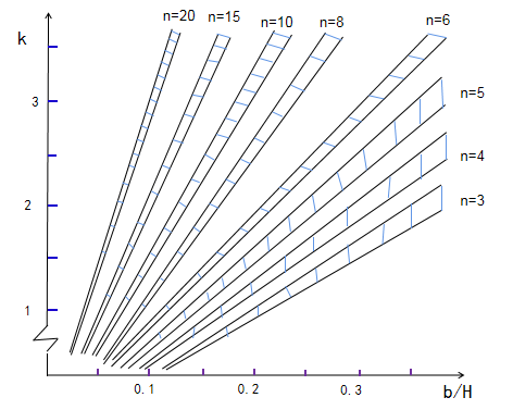
Figure 4 Grid fin surface mesh and spatial flow field
Design Methods — Testing and CFD Simulation
1. Both Testing and CFD Are Required
For complex configurations, experimental data remain the foundation for establishing aircraft performance. Ground-based high- and low-speed wind tunnel testing is a major element of aerodynamic design.
Modern development has shown that effective use of CFD can significantly reduce design costs and shorten development cycles.
2. The Necessity of Testing: Limitations of CFD
Despite maturity in CFD engineering, model-level wind tunnel testing has not diminished. Wind tunnel testing remains essential because CFD can be inaccurate for some conditions or computationally expensive. Examples:
(1) High-lift configurations during takeoff and landing, particularly moment characteristics, show significant differences between CFD and wind tunnel results.
(2) At high angles of attack near stall, CFD predictions are often lower than wind tunnel values.
(3) Simulation of unsteady pulsations using LES or DES requires computational resources and time that can exceed wind tunnel testing.
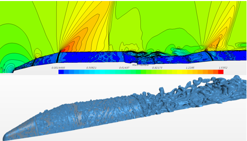
Figure 5 Transonic pulsating pressure field for a cone-cylinder-boattail rocket shape
(4) Due to inherent CFD modeling limitations, many details differ from real flow fields. Complex interactions such as shock-vortex interference and component-to-component flow interference still require wind tunnel testing.
3. CFD Enables Optimized Aerodynamic Layouts
Beyond serving as a "numerical wind tunnel," CFD can simulate scenarios difficult or impossible for wind tunnel tests, for example:
(1) Rapid closed-loop development of complex-layout aerodynamic concepts
(2) Parametric optimization of components and layout
(3) Multidisciplinary integrated design
(4) Conditions that wind tunnel testing cannot cover or that would be prohibitively costly to test
Design Tools — Meshing and Solvers
1. Structured Mesh or Unstructured Mesh
Mesh is the largest factor affecting results. Whether structured or unstructured, meshes need good node distribution on surfaces and in space, which depends on understanding the flow in the solution domain. This explains why the same software can produce different results even when generating unstructured meshes.
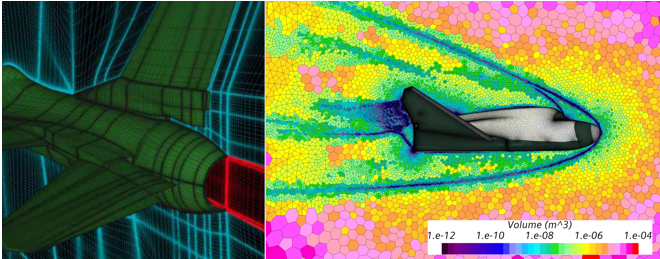
Figure 6 Typical structured and unstructured meshes
High-quality structured meshes are time-consuming but yield good results and require experience. In most applications they are being replaced by unstructured meshes. However, because structured meshes capture near-wall viscous effects more accurately, aerodynamic heating simulations still often rely on structured meshes.
2. Choice of Solver
With many solvers available, selection depends on the flow conditions to be simulated. Choosing the right solver requires engineering experience and practice. Developing turbulence models or limiters without strong mathematical or programming skills can be very difficult. For layout design engineers, it is more important to choose the right tool than to develop one.
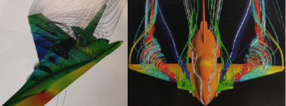
Figure 7 Vortex development induced by boattails and canards
3. Is the Tool at Fault, or the User?
When simulated aerodynamic or aerothermal results match wind tunnel data well for some engineers but not others, the reasons are typically either that the chosen tools are inappropriate for the conditions or that the user has not mastered them.
"The tool is inadequate" means the mesh generation tool or solver selected is not suitable for the target conditions.
"The user is inadequate" means the tools are capable but not properly applied. Examples include improper boundary-layer mesh (different solvers require different Y+), or attempting to simulate shock/boundary-layer interaction unsteadiness with DES without appropriate settings.

Figure 8 Quasi-structured representation of an S-duct intake simulated with an LES model