Introduction
In recent years, demand for unmanned aerial vehicles (UAVs) has grown rapidly across agriculture, accident investigation, military, construction, mining, and surveying. The reliability of a UAV's navigation solution is critical to operational safety. As a result, compact, lightweight, and low-cost navigation and positioning technologies for UAVs have become research priorities.
GPS and GNSS Basics
GPS stands for Global Positioning System and originated as a U.S. military project. In addition to GPS, other global navigation satellite systems exist: China operates BeiDou, Russia operates GLONASS, and the European Union operates Galileo. The positioning principles across these systems are essentially the same. These systems provide both positioning and precise timing, with accurate timing supplied by satellite atomic clocks. Position and time are closely linked in satellite navigation.
Consider a UAV equipped with a GPS receiver. The UAV's spatial coordinates (X, Y, Z) and its time coordinate T are unknown. Satellites broadcast ephemeris data containing each satellite's precise spatial coordinates (X1, Y1, Z1) and time T1. From the satellite data, the distance between the UAV and a satellite can be obtained two ways: geometrically from coordinates using the Euclidean distance formula, and by converting signal travel time into distance using the speed of light (approximately 3×10^8 m/s) multiplied by the travel time (T - T1). Equating these two forms produces an equation relating X, Y, Z, and T.
Each satellite provides one such equation. Since there are four unknowns (X, Y, Z, T), at least four satellites are required to solve for the UAV's position and clock offset. The main practical challenge in satellite positioning is error, because atmospheric effects and other factors can slightly delay signal propagation; even a small delay yields a significant position error given the high speed of light. Typical standalone GPS errors are on the order of several meters to tens of meters.
Differential Techniques and Error Correction
To reduce positioning errors, differential GPS techniques can be used to greatly improve accuracy. A reference station at a known coordinate near the UAV receives the same satellite signals and computes its observed coordinate errors by comparing measured coordinates with its known coordinates. The reference station then transmits the error corrections or real-time carrier phase measurements to the UAV via a data link or mobile communication network. The UAV applies these corrections to improve its position estimate. Alternatively, UAVs can receive correction services from professional precise positioning service providers via mobile networks.
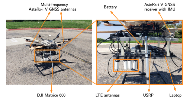
Figure 1 Experimental hardware setup
GNSS Limitations for UAVs
GNSS is widely used outdoors and supports centimeter-level positioning modes such as RTK (real-time kinematic) and PPP (precise point positioning). However, GNSS alone may not be a decisive navigation element for future UAV systems due to:
- High signal attenuation in urban canyons, which can render GNSS unreliable for data-linking, air traffic management, and accident investigation scenarios.
- Susceptibility to intentional interference and spoofing, which can seriously disrupt both military and civilian UAV operations.
Researchers and practitioners therefore use sensor fusion to meet the UAV constraints of small size, light weight, and low cost while achieving robust and accurate navigation. Based on literature, three main UAV navigation approaches are commonly used.
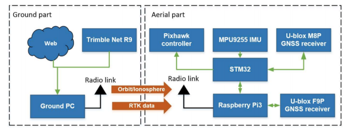
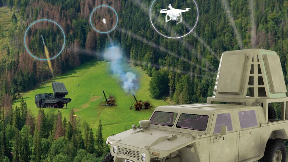
Figure 2 Operational modes
1. RTK with MEMS Loose Coupling
Low-cost UBlox GNSS receivers have been evaluated for single-frequency RTK, showing centimeter-level position accuracy in some setups. Integrating RTK with low-cost MEMS inertial sensors can improve position and attitude estimation and help mitigate weak-signal scenarios. However, RTK has limitations, notably a restricted operational range determined by the baseline length to the base station. For single-frequency RTK, resolving carrier phase ambiguities becomes difficult when baseline lengths approach 15 km or longer. Under loose coupling and long baselines, when RTK precision degrades, the positioning algorithm may not provide a robust and accurate result for the UAV.
2. PPP with MEMS Loose Coupling
PPP has been demonstrated to achieve centimeter-level accuracy in some testbeds, but those results often rely on post-processing or high-end dual-frequency receivers, which conflicts with small, lightweight UAV requirements. A study on a real-time low-cost single-frequency PPP (SFP) loosely coupled with MEMS INS used a quadrotor equipped with a UBlox M8P single-frequency GNSS receiver and an economy MEMS IMU (MPU9250) on a Pixhawk. PPP correction data were transmitted via a 3DR radio link. Because standard cycle-slip detection methods for dual-frequency receivers are not applicable to single-frequency low-cost receivers, the researchers used a Doppler-aided single-frequency cycle-slip detection method. The reported positioning accuracy reached decimeter level in their experiments.
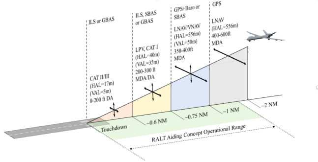
Figure 3 Radar altimeter assistance range
3. Radar-Altimeter-Assisted GNSS Positioning
Using a radar altimeter (RALT) to assist GNSS aims to improve GNSS accuracy, integrity, and continuity to meet strict landing requirements. High-precision vertical range data from the RALT can improve the overall 3D position solution. Typical implementations combine three subsystems: a selected GNSS constellation (often dual-frequency GPS or GPS augmented by SBAS), a commercial RALT providing above-ground-level (AGL) height measurements, and a terrain database used to convert AGL into mean sea level (MSL) height. Each subsystem contributes to system accuracy, and understanding sensitivity to each component is necessary to ensure performance requirements are met.
Example: Dual-Antenna Heading Replacement for Rover
A practical example involves replacing an unreliable magnetic compass on an unmanned ground vehicle (UGV) with a dual-antenna GNSS heading solution. Magnetic compasses are prone to hard-iron and soft-iron interference and require frequent calibration. Using a dual-antenna heading board such as a NovAtel dual-antenna heading module provides direct heading output, eliminating compass calibration and avoiding magnetic interference, which improves system stability. The approach can also be applied to UAVs, where heading information is often more stable at altitude.
The UGV system in this example includes the following elements:
- Commercial centimeter-level RTK positioning service
- Outdoor LiDAR-based obstacle avoidance using the Vector Field Histogram (VFH) method
- Dual-antenna GNSS heading to replace magnetic compass heading
- EKF-based attitude and position estimation
- ROS and MAVLink interfaces
With appropriate command inputs such as desired speed or target position, the vehicle chassis can execute obstacle avoidance and other complex behaviors.