Overview
Aerial photography with unmanned helicopters uses an unmanned aerial vehicle as the flight platform and high-resolution camera systems to capture remote sensing images. With onboard image compression, automatic transmission, and preprocessing functions, these systems are applied in environmental monitoring, mineral exploration, land use surveys, crop monitoring and yield estimation, natural disaster monitoring and assessment, urban planning and municipal management, public safety, defense, and digital earth applications.
Consumer drones sold to Western markets must meet CE and FCC requirements to gain market access. EMC design for multiple subsystems on a drone (EMS and EMI) directly affects overall system stability, including image data loss, GPS positioning, and flight distance control. Governments worldwide have established mandatory EMC regulations, so electronic products must comply with the applicable national EMC standards to be sold, for example CE in the EU, FCC in the US, NEBC, VCCI in Japan, and China's 3C (CCC) certification. For electromechanical products such as drones, regulators are developing product-specific EMC test and certification standards.
Strong EMC design capability is essential for a reliable drone. This article analyzes drone EMC from a practical design and testing perspective for this multi-system integrated hardware product.
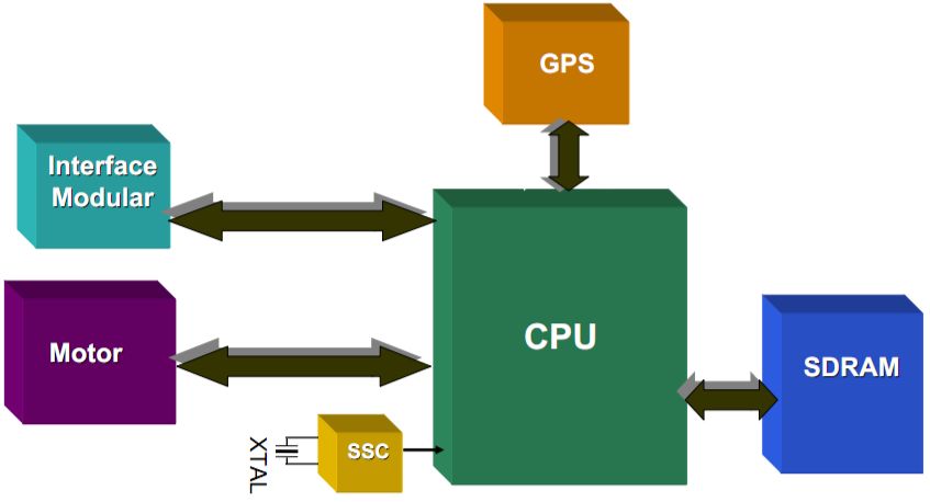
Drone Platform Architecture
Flight controllers
Notable flight controllers that have appeared on the market include DJI flight controllers, ZeroTech flight controllers, MWC flight controllers, and APM flight controllers.
EMI Status and Key Issues
1. EMI status
- EMI exceedances can prevent products from passing EMC certification, blocking exports.
- EMI exceedances can degrade wireless transmission signal quality (2.4 GHz, 5.8 GHz).
2. Main EMI sources in drones
- EMI from the camera/gimbal assembly.
- Clock sources and their harmonics/multiples in the flight-control system.
- EMI generated by motors.
- Radiated emissions originating from the power subsystem.
EMC Considerations and Near-field Testing
The following example uses a small electrically driven drone to discuss EMC issues and to measure near-field electromagnetic interference from key power and control units.
1. EMI types
Electromagnetic interference is classified as radiated EMI and conducted EMI. Conducted interference typically occurs at lower frequencies and propagates via conductive media between circuits. Radiated interference typically occurs at higher frequencies and propagates as electromagnetic waves. For AC-powered equipment, conducted EMI limits protect the power grid and other devices connected to it. Drones are battery powered, so power and signal connections between onboard subsystems are via wiring; conducted coupling between the propulsion unit and other subsystems depends on the specific system. Video transmitters use RF transmitters and antennas to radiate signals at certain frequencies and power levels. On PCBs, high-frequency traces, IC pins, and connectors can act as unintended antennas and radiate EMI, potentially affecting other onboard circuits. During design and debugging, near-field testing of each subsystem helps locate radiating sources and quantify radiated interference for targeted mitigation.
2. Near-field EMI testing
Radiated EMI testing includes near-field and far-field measurements. Far-field testing is performed in RF chambers with dedicated receive antennas and receivers to measure total radiated emissions at a distance. Near-field testing is essential during R&D and troubleshooting because it provides spatial information about which components, pins, or traces are sources of interference, allowing targeted mitigation measures. Typical equipment for near-field EMI testing includes a spectrum analyzer and near-field probes.
Below are near-field EMI tests performed on a flight-control board, an electronic speed controller (ESC), and a brushless motor using a spectrum analyzer and near-field probes.
3. Near-field test of the flight-control board
The flight-control board contains multiple ICs connected via SPI, I2C, and parallel digital IO buses. Use appropriately sized near-field probes to scan each device and evaluate individual EMI contributions. The IMU on this flight-control board is an MPU-6000 9-axis motion sensor. The near-field EMI measured on this sensor resembles clock-related emissions.
The board also uses an STM32F427 Cortex-M4 processor and other components. Apply the same near-field scanning procedure to each device to map their EMI signatures.
Case Studies
1. Camera head EMI
(1) CCD camera head (example: SONY effio solution)
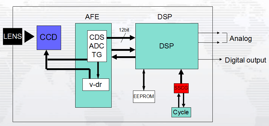
Potential issues:
- Clock and multiplier interactions between the DSP and AFE.
- Clock outputs from the DSP and their harmonics.
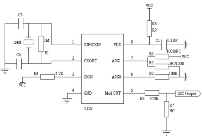
Mitigation: Use a spread-spectrum IC on the DSP crystal.
(2) CMOS camera head
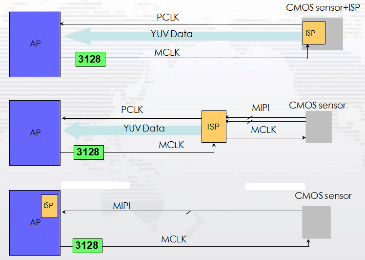
Possible issue: MCLK and PCLK base frequencies and harmonics from the camera can cause radiated emission exceedances.
Mitigation: Adding spread-spectrum modulation on MCLK can effectively reduce the base frequency and harmonic radiated emissions from MCLK and PCLK.
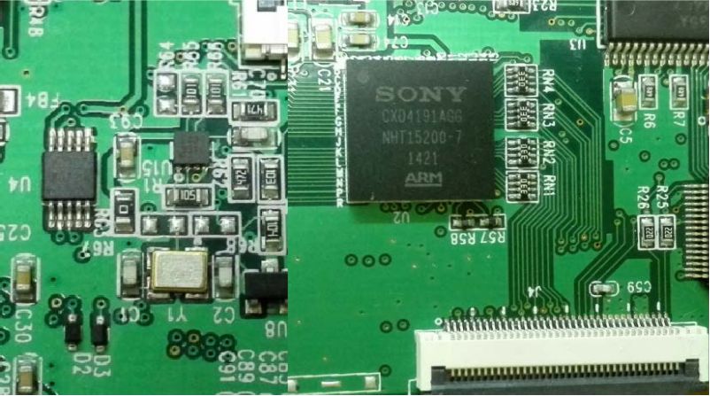
(3) Application example
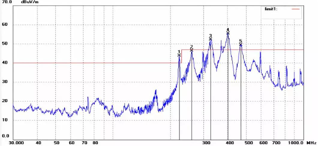
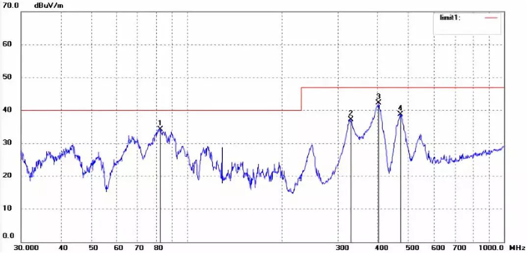
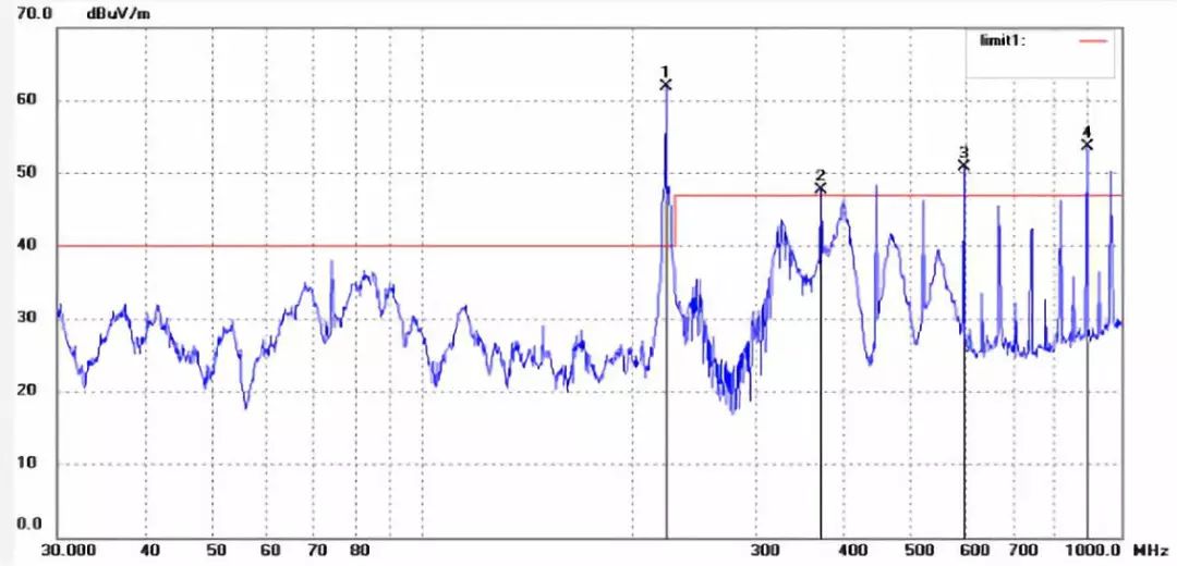
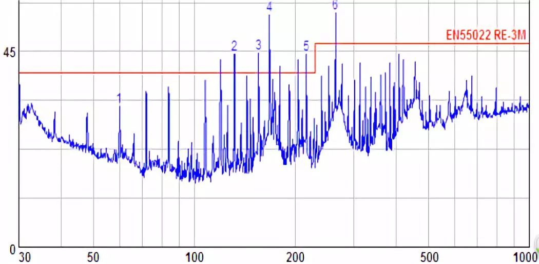
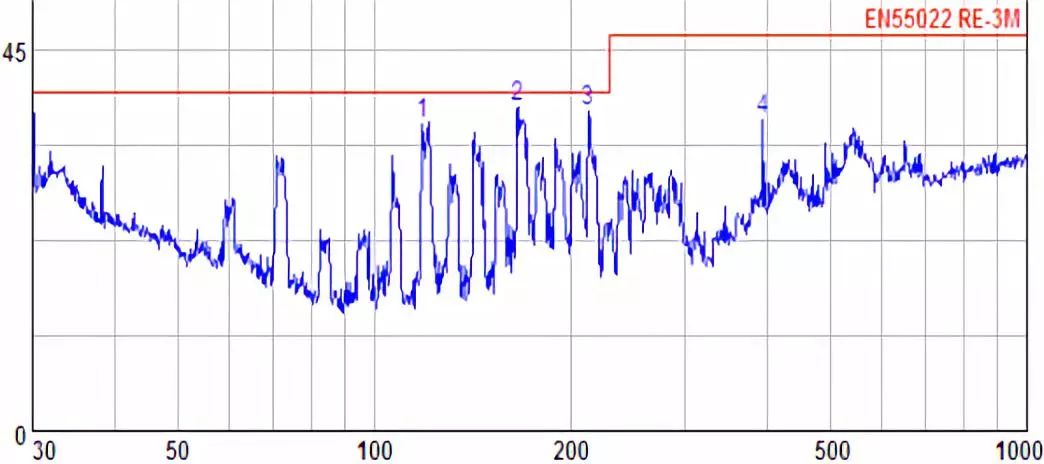
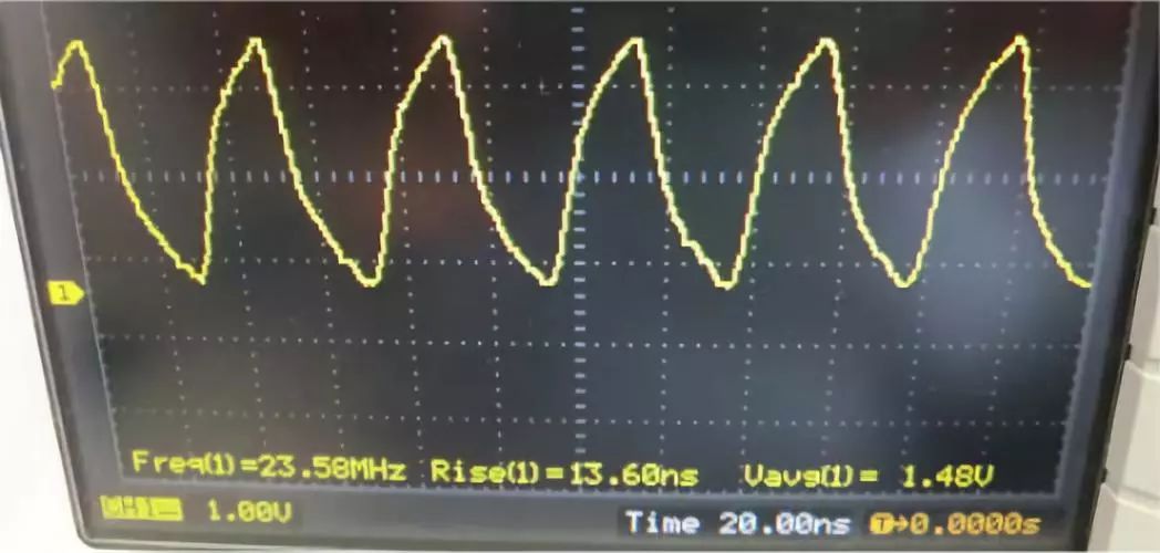
Issue: A SONY DSP (CXD4191AGG) produced harmonics of a 74 MHz output clock.
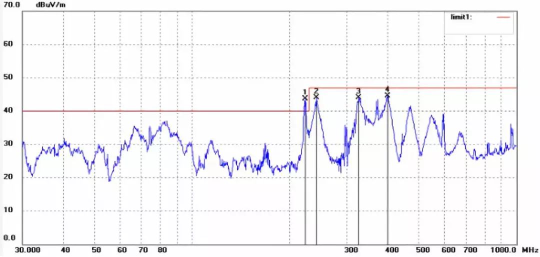
After adding a spread-spectrum IC the spectrum comparison shows a marked reduction in discrete harmonics. The original spectrum contained many discrete, excessive lines; with spread-spectrum, the overall level decreased and discrete lines were reduced.
2. Flight-control clocks and harmonics
Possible issue: Radiated emissions from the main clock fundamental and its harmonics.
Mitigation: Use spread-spectrum ICs on the clock source.
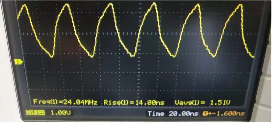
After adding spread-spectrum, measurements show a clear overall reduction in radiated emissions and preserved signal integrity. Signal comparisons before and after spread-spectrum show improved integrity.
3. Motor-induced EMI
Possible issue: Noise and interference generated by motor rotation.
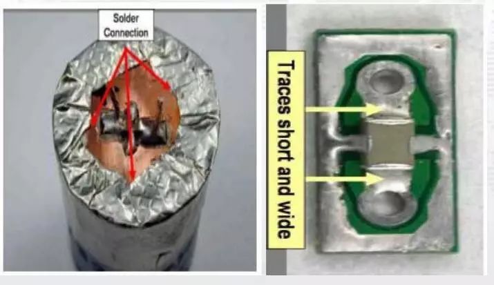
Mitigation: Use a BDL EMI filter close to the motor connection.
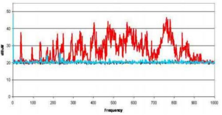
Measured EMI before and after adding a BDL filter shows a significant reduction in radiated emissions.
BDL (Balanced Dual-Line EMI Filter) has been widely applied in communications, networking, military, aerospace, medical, consumer electronics, and connector applications. Structurally, a BDL filter appears similar to a conventional EMI filter composed of two Y capacitors and one X capacitor. Key distinguishing features include additional paired reference electrodes that form a Faraday-shield or coaxial-like structure, converting a single-ended component into a balanced dual-ended component, and design rules that reduce external radiation and minimize ESR and ESL. The balanced configuration provides matched line-to-ground capacitance, temperature and voltage common-mode cancellation, and symmetric aging of the two electrodes.
4. Power-related radiated emission suppression
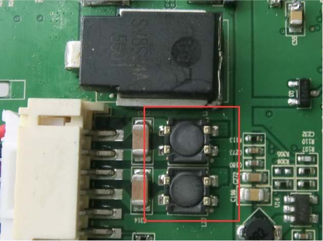
Possible issue: Ground imbalances between boards causing common-mode interference.
Mitigation: Use dedicated high-frequency filters to isolate and suppress common-mode currents.
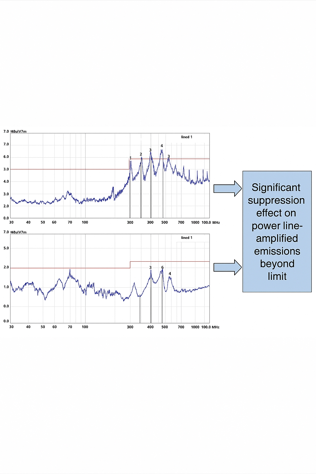
Comparison of impedance characteristics between high-current common-mode chokes and traditional common-mode chokes is shown below.
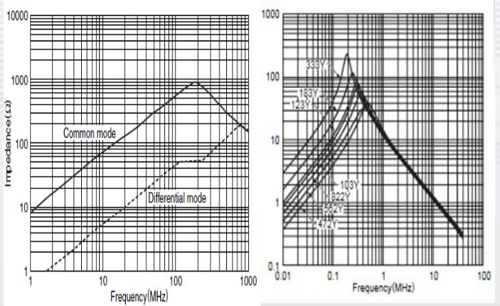
Measurement comparisons show effective suppression of emission bands amplified via power lines.