Introduction
Ball Grid Array (BGA) components represent a cornerstone in modern electronics assembly, enabling high-density interconnections essential for advanced devices like processors and memory modules. These packages feature an array of solder balls on the underside, which connect directly to the printed circuit board (PCB) pads during reflow soldering. Proper BGA assembly demands precision at every stage to avoid defects such as voids, bridges, or misalignment that can compromise reliability. Inspection plays a critical role, particularly with techniques like X-ray inspection of BGAs, to verify joint integrity without destructive testing. This guide explores the full process, from solder paste printing for BGAs to BGA rework, offering practical insights for electric engineers tackling real-world production challenges. Mastering these elements ensures robust performance in high-stakes applications.
What Is BGA Technology and Why It Matters
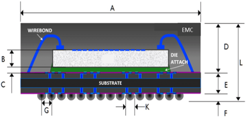
BGA technology distributes connections across the entire bottom surface of the package, maximizing pin count while minimizing inductance and improving signal integrity compared to perimeter-lead packages. This design supports finer pitches, often below 1 mm, making it ideal for compact, high-performance boards in telecommunications, computing, and automotive electronics. However, the hidden nature of solder joints under the package body complicates visual inspection and increases risks from thermal mismatches or warpage during assembly. Electric engineers must prioritize BGA assembly to meet reliability standards, as failures here can lead to field returns or safety issues. Key target areas include solder paste printing for BGAs, precise component placement, optimized BGA soldering profiles, and thorough post-reflow checks. Understanding these ensures consistent yield and longevity in demanding environments.
The relevance intensifies with shrinking geometries and lead-free mandates, where even minor process variations amplify defects. Engineers often troubleshoot issues like head-in-pillow or non-wet opens stemming from poor paste volume or placement accuracy. By aligning processes with industry guidelines, such as those in IPC-7095E, teams mitigate these risks effectively. This standard provides detailed implementation for BGA design and assembly, emphasizing process controls that directly impact joint quality.
Key Stages in BGA Assembly Process
Solder Paste Printing for BGAs
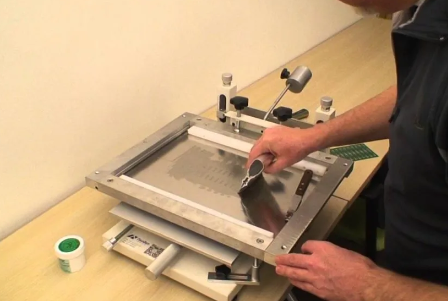
Solder paste printing sets the foundation for successful BGA attachment, requiring stencils with laser-cut apertures tailored to the ball grid pattern. Fine-pitch BGAs demand thinner foils and precise squeegee pressure to deposit uniform paste volumes without bridging or insufficient deposit. Engineers troubleshoot common issues like paste smearing by optimizing stencil thickness and cleaning cycles, ensuring apertures release cleanly. Volume consistency proves vital, as underfill leads to open joints while excess causes shorts during reflow. Verification via solder paste inspection (SPI) systems catches deviations early, correlating paste height and area to expected profiles.
Stencil design incorporates trapezoidal apertures for better paste release in high-density arrays, reducing residue buildup over runs. Process parameters, including snap-off distance and print speed, fine-tune deposition for various BGA pitches. Troubleshooting often reveals that humidity affects paste viscosity, necessitating controlled environments. This stage directly influences downstream steps like component placement and reflow success.
Component Placement for BGAs
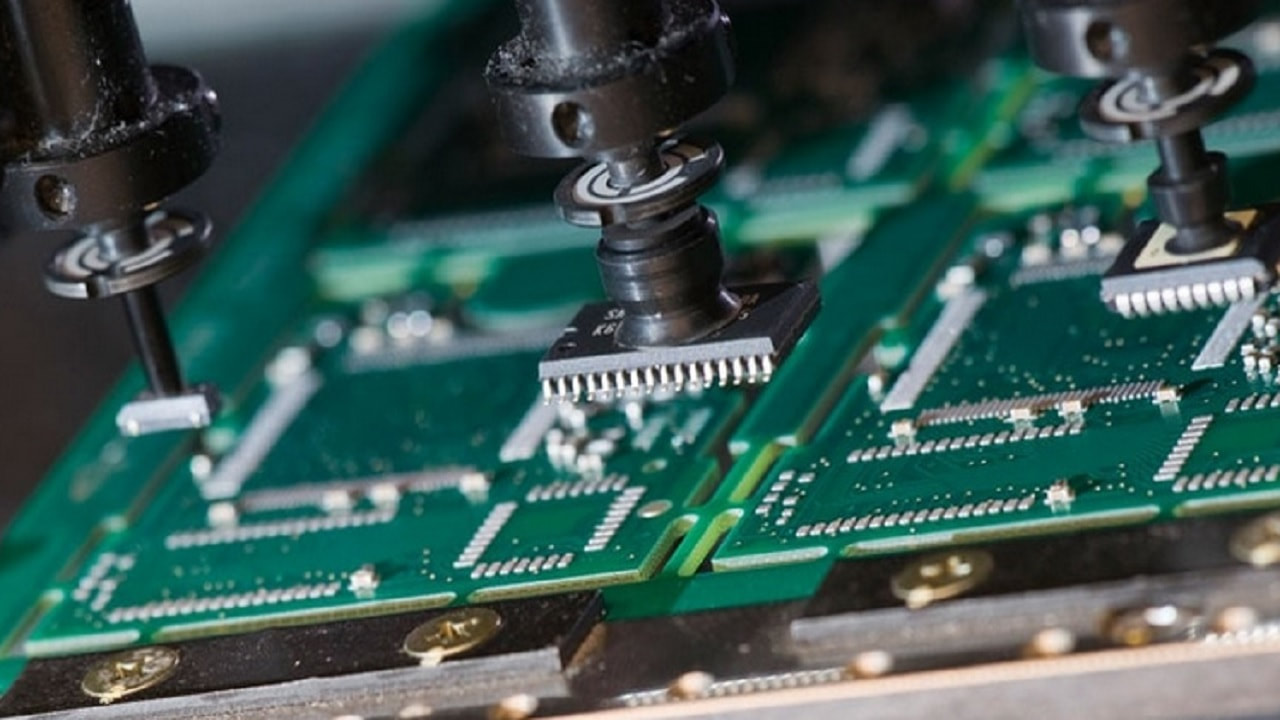
Component placement demands sub-micron accuracy for BGAs, as even slight offsets misalign balls with pads, leading to bridging or opens post-reflow. High-speed pick-and-place machines use vision systems to align fiducials on both the BGA and PCB, compensating for rotational errors. Engineers adjust nozzle vacuum and placement force to handle delicate packages without damaging balls or causing warpage. Self-alignment during reflow helps, but initial positioning must stay within tight tolerances, typically centering the BGA shadow over pads.
Troubleshooting placement defects involves analyzing machine logs for force spikes or vision offsets, often tracing back to board warpage or sticky paste. For large BGAs, sequential placement or edge clamping prevents flexing. Post-placement verification confirms no shifts before entering the reflow oven. Precision here minimizes rework needs and supports high-volume production.
BGA Soldering Profile and Reflow Process
The BGA soldering profile defines the thermal excursion through preheat, soak, reflow, and cooling zones to form reliable joints without damaging components. Profiles follow classifications from IPC/JEDEC J-STD-020F, accounting for moisture sensitivity to prevent popping or delamination. Preheat ramps gradually to activate flux, while soak evaporates solvents evenly across the board. Reflow melts balls into liquidus, allowing wetting and coalescence, followed by controlled cooling to avoid thermal shock.
Engineers profile ovens using thermocouples on test boards with BGAs, iterating to achieve uniform heating across large panels. Common troubleshooting targets insufficient peak temperature causing non-melts or excessive time above liquidus leading to intermetallic growth. Nitrogen atmospheres reduce oxidation, enhancing joint fillet formation. Monitoring warpage during ramp-up prevents ball collapse from package-board mismatch.
Inspection Techniques for BGA Assemblies
Visual inspection falls short for BGAs due to obscured joints, making X-ray inspection of BGAs indispensable for detecting voids, bridges, and head-in-pillow defects. 2D X-ray reveals top-down views of solder distribution, while 3D CT slices provide volumetric analysis for precise void percentages. Engineers calibrate systems for contrast optimized to alloy density, scanning full arrays efficiently. Automated analysis flags anomalies against acceptability criteria, streamlining qualification.
Other methods like acoustic microscopy complement X-ray for underfill voids, but X-ray remains primary for joint integrity. Troubleshooting excessive voids often links back to paste volume or profile issues, prompting process tweaks. Slice imaging helps differentiate true opens from lifted balls. Consistent inspection protocols build confidence in assembly quality.
BGA Rework Procedures and Best Practices
BGA rework addresses defects or upgrades, involving controlled removal, site preparation, and replacement to restore functionality. Per IPC-7711/7721C guidelines, infrared or convection heating profiles mimic reflow but localize energy to the site. Engineers preheat the board globally, then apply focused heat to melt balls without reflowing neighbors. Post-removal, site redress uses drag soldering or chemical cleaners to expose clean pads.
Reballing restores sphere geometry on new BGAs using flux and miniature stencils, verified for uniformity before placement. Replacement follows a tailored profile, with post-rework X-ray confirming joint quality. Troubleshooting warped sites requires planarity checks, often using interposers. Success hinges on thermal simulation and profilometry to match original assembly conditions.
Troubleshooting Common BGA Assembly Issues
Electric engineers frequently encounter warpage-induced misalignment, mitigated by low-stress laminates and symmetric layouts. Voids from flux entrapment respond to extended soak times or finer paste powders. Bridging traces to paste bridging, fixed by refined stencil apertures or reduced print pressure. Non-wets signal pad contamination, addressed via plasma cleaning pre-print.
Data logging across lines correlates defects to parameters, enabling predictive adjustments. Cross-sectioning samples validates X-ray findings, refining criteria. Layered troubleshooting—process, materials, equipment—systematically isolates root causes.
Conclusion
BGA assembly and inspection demand integrated precision across solder paste printing for BGAs, component placement, BGA soldering profiles, X-ray checks, and BGA rework. Adhering to standards like IPC-7095E, J-STD-020F, and IPC-7711/7721C ensures reliable joints in high-density designs. Practical troubleshooting empowers engineers to optimize yields and minimize downtime. Implementing these practices elevates assembly from routine to robust, supporting innovation in electronics.
FAQs
Q1: What key factors influence a reliable BGA soldering profile?
A1: The BGA soldering profile must balance preheat to remove moisture per J-STD-020F classifications, soak for flux activation, and reflow peak for complete melting without overheating. Engineers monitor ramp rates to avoid thermal shock and use nitrogen to minimize oxidation. Profiling with thermocouples on production boards verifies uniformity, preventing voids or delamination common in moisture-sensitive packages. Adjustments target specific alloy behaviors for consistent joint formation.
Q2: How does X-ray inspection of BGAs detect solder defects?
A2: X-ray inspection of BGAs penetrates the package to image joint voids, bridges, and alignment non-destructively. 2D views show solder mass distribution, while 3D tomography quantifies void volumes against criteria. Engineers interpret contrasts for head-in-pillow or opens, correlating to process issues like paste volume. Automated thresholds flag outliers, enabling rapid feedback for reflow tweaks.
Q3: What are best practices for solder paste printing for BGAs?
A3: Solder paste printing for BGAs requires stencils with precise apertures matching ball grid pitch, using laser-cut foils for clean release. Maintain consistent squeegee speed and pressure to achieve uniform deposits, verified by SPI. Control environment to stabilize paste rheology, avoiding smears from humidity. Troubleshooting underfill involves finer powder types or nanocoatings on stencils.
Q4: When is BGA rework necessary, and how to execute it effectively?
A4: BGA rework becomes essential for detected defects like high voids or electrical fails post-inspection. Follow IPC-7711/7721C for profiled removal using localized heat, site cleaning, reballing, and replacement. Preheat boards to prevent warpage, and profile new attachment matching original reflow. Post-rework X-ray confirms integrity, minimizing yield loss.
References
IPC-7095E - Design and Assembly Process Guidance for Ball Grid Arrays (BGAs). IPC, 2024
IPC/JEDEC J-STD-020F - Moisture/Reflow Sensitivity Classification for Nonhermetic Surface Mount Devices. IPC/JEDEC, 2022
IPC-7711C/7721C - Rework, Modification and Repair of Electronic Assemblies. IPC, 2018


