Introduction
Automated Optical Inspection (AOI) stands as a cornerstone in modern PCB manufacturing, enabling rapid and precise defect detection on assembled boards. For electric engineers tasked with quality control, mastering AOI equipment programming unlocks efficiency gains and reduces false calls. This comprehensive AOI equipment programming tutorial walks through the process systematically, from initial setup to optimization. Whether you are programming for high-volume production or prototype verification, understanding these steps ensures compliance with rigorous industry standards. By following this guide, engineers can implement reliable inspection routines that align with factory demands. The focus here remains on practical, factory-driven insights to elevate your workflow.
What Is AOI Equipment Programming and Why It Matters
AOI equipment programming involves configuring software to define inspection parameters, algorithms, and acceptance criteria for PCB assemblies. At its core, it translates design data and quality requirements into machine-readable instructions that guide cameras and image processing to identify defects like misalignments, soldering issues, or missing components. This process matters because manual inspection cannot match the speed and consistency of AOI, especially in surface-mount technology lines where throughput is critical. Engineers benefit from reduced rework costs and higher yield rates, directly impacting production timelines. In high-reliability sectors such as aerospace and automotive, precise programming prevents escapes of defects that could lead to failures. Ultimately, effective AOI equipment programming software integration ensures traceability and supports continuous process improvement.

Fundamental Principles of AOI Systems
AOI systems rely on high-resolution cameras capturing images under controlled lighting conditions to compare against reference data. Key mechanisms include 2D imaging for component presence and solder joint analysis, with some advanced setups incorporating 3D profiling for height measurements. Algorithms such as pattern matching, edge detection, and color segmentation process these images to flag anomalies. Lighting configurations, including coaxial, low-angle, and side lighting, are programmed to highlight specific features like pad visibility or bridge detection. Engineers must grasp these principles to avoid programming pitfalls, such as overexposure washing out fine-pitch components. Alignment via fiducial marks ensures sub-pixel accuracy, forming the backbone of reliable inspections.
Programming begins with understanding resolution limits, typically tied to pixel density and optics, which dictate detectable defect sizes down to 10 microns in fine-pitch assemblies. Data flow involves real-time processing where software applies filters to minimize noise from reflections or shadows. Calibration routines verify system performance against known standards, maintaining consistency across shifts. These technical foundations empower engineers to customize inspections for diverse board types, from rigid FR-4 to flexible circuits. By aligning programming with these mechanisms, false accepts and rejects drop significantly.
Step-by-Step AOI Equipment Programming Tutorial
Step 1: Preparation and Data Import
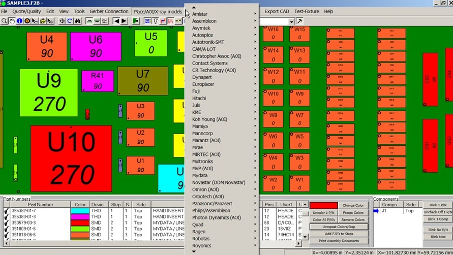
Start by gathering essential inputs, including Gerber files, bill of materials (BOM), and centroid data from the PCB design phase. Import these into the AOI equipment programming software to generate a digital twin of the board. Verify layer alignments and component placements to prevent offsets during inspection. Define board parameters like dimensions, panelization, and fiducial locations, ensuring at least two to three fiducials per panel for robust alignment. This foundational step sets the stage for accurate teaching and minimizes downstream errors. Engineers should cross-check imports against physical prototypes to confirm data integrity.
Step 2: Board Setup and Mechanical Configuration
Configure the conveyor system and Z-axis height to accommodate board thickness variations, typically ranging from 0.8 mm to 3.2 mm for standard rigid PCBs. Program stoppers and flip stations if inspecting both sides, sequencing top then bottom scans. Set scan speed based on board complexity, balancing throughput with resolution needs. Calibrate lighting presets for different surface finishes, such as HASL or ENIG, to optimize contrast. Test runs with dummy boards validate mechanical stability before full programming. This methodical setup ensures uninterrupted flow in production environments.
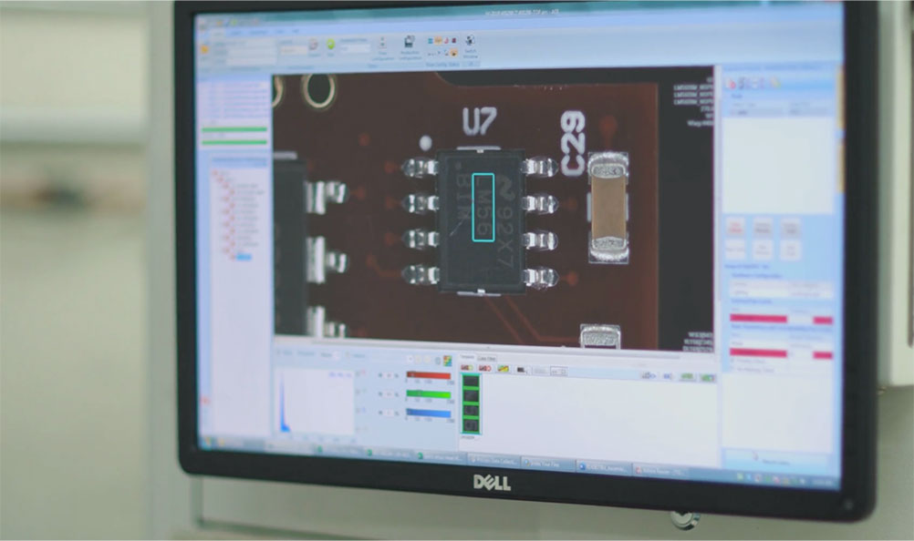
Step 3: Teaching Mode and Golden Image Creation
Enter teach mode to capture reference images, or golden samples, from known good boards under production lighting. The software guides manual or semi-automated teaching, where engineers select regions of interest for components, vias, and solder joints. Assign inspection types, such as presence/absence for passives or polarity checks for diodes. Build a component library by teaching common parts, storing shape, size, and orientation data for reuse. Iterate captures to account for process variations like paste volume differences. Golden images serve as the benchmark, with tolerances programmed around nominal values to reflect real-world assembly tolerances.
Step 4: Defect Classification and Rule Setting
Define defect classes aligned with industry criteria, categorizing issues into no-call, false call, missing part, or bridge. Set thresholds for each, using metrics like area deviation or brightness gradients for solder inspection. Program advanced rules, such as bridging only on adjacent pads or lifted leads exceeding a pitch fraction. Integrate statistical process control by linking calls to upstream machines for root cause analysis. Validate rules through trial runs on mixed good/bad boards, adjusting sensitivity to achieve target false call rates below 500 per million inspections. This step transforms raw programming into a discerning quality gate.
Step 5: Optimization and Validation
Run optimization algorithms within the software to refine parameters, reducing computation time while maintaining detection rates. Simulate inspections on varied boards to stress-test rules against rotations or scaling. Validate against physical lots, logging call data for statistical analysis like Cpk values on critical features. Fine-tune for specific defects, such as tombstoning in reflow processes, by adjusting edge detection weights. Export programs for offline review and version control, ensuring traceability. Final validation confirms alignment with standards like IPC-A-610 for acceptability criteria.
AOI Equipment Programming Methods and Tips
Several methods enhance programming efficiency, including template-based approaches for similar board families and scripting for batch adjustments. Rule-based methods excel for standard inspections, while AI-assisted learning suits complex boards with high variability. Among AOI equipment programming tips, always prioritize fiducial redundancy to handle warpage, programming offsets dynamically. Use multi-threaded processing in software to handle high-resolution 3D data without bottlenecks. Document parameter changes in a revision log to support audits. Leverage post-inspection analytics to iteratively improve programs, targeting under 1% escape rates.
Best practices include modular programming, where common inspections like BGA balling are pre-built libraries. Schedule regular recalibrations per shift to counter environmental drifts in temperature or humidity. Train teams on software updates to incorporate new algorithms without disrupting lines. For high-mix environments, employ quick-teach modes to slash setup times from hours to minutes. Integrating with MES systems automates program selection by job number, streamlining factory operations. These AOI equipment programming best practices, rooted in factory realities, boost overall equipment effectiveness.
Troubleshooting Common AOI Programming Challenges
False calls often stem from unaccounted reflections on shiny finishes, resolved by tweaking diffuse lighting angles. Missing detections on low-contrast vias require enhanced edge enhancement filters. Board warpage exceeding 0.75% pitch can misalign fiducials, addressed by programming adaptive alignment zones. Software glitches during import may arise from incompatible file formats, necessitating standardized exports from design tools. Overly stringent tolerances inflate rejects, balanced by referencing J-STD-001 guidelines for solder joint criteria. Systematic logging and root cause mapping turn these issues into process refinements.
In case studies from high-volume lines, reprogramming for fine-pitch QFNs cut escapes by focusing on fillet height rules. Troubleshooting multi-layer boards involves isolating top-side calls from bottom, using side-view cameras. Environmental factors like dust mandate cleanroom protocols alongside programming clean-up filters. Collaborative reviews between programming and process engineers accelerate fixes. These insights highlight proactive programming as key to sustained quality.
Conclusion
Mastering AOI equipment programming empowers electric engineers to safeguard PCB quality amid rising complexity. This guide outlined preparation, teaching, rules, and optimization, emphasizing factory-proven methods. By adhering to best practices like modular libraries and validation runs, you minimize defects and maximize throughput. Standards such as IPC-A-610 provide the framework for reliable criteria. Implement these steps iteratively to adapt to evolving production needs. Elevate your expertise and drive manufacturing excellence.
FAQs
Q1: What are the essential steps in an AOI equipment programming tutorial?
A1: The core steps include data import from Gerber and BOM files, board setup with fiducials, golden image teaching, defect rule definition, and validation runs. Engineers start with mechanical calibration for conveyor and lighting, then build component libraries for reuse. Optimization follows trial inspections to refine thresholds. This sequence ensures accurate defect detection in line with factory standards. Expect setup times of 1-4 hours depending on board complexity.
Q2: How does AOI equipment programming software handle complex assemblies?
A2: AOI equipment programming software uses pattern matching and 3D profiling to inspect fine-pitch components and solder joints. Import design data to overlay expectations, then teach regions for polarity and bridging checks. Advanced algorithms adapt to variations like warpage via fiducial compensation. Validation against mixed lots confirms low false calls. Integration with libraries speeds multi-variant programming.
Q3: What AOI equipment programming tips reduce false calls?
A3: Key tips involve balanced lighting for surface finishes, tolerance margins per IPC guidelines, and statistical tuning post-trial. Prioritize fiducials for alignment and modular rules for reusability. Analyze call logs to adjust sensitivities iteratively. Clean golden images eliminate artifacts. These practices achieve rates under 500 PPM in production.
Q4: What are effective AOI equipment programming best practices for high-volume lines?
A4: Best practices include version-controlled programs, automated MES linking, and shift calibrations. Use scripting for batch tweaks and AI aids for optimization. Align rules with J-STD-001 for soldering criteria. Document changes for audits. This sustains high uptime and yield in demanding environments.
References
IPC-A-610H - Acceptability of Electronic Assemblies. IPC, 2017
J-STD-001H - Requirements for Soldered Electrical and Electronic Assemblies. IPC, 2018


