Introduction
Assembling printed circuit boards at home has become more accessible for electronic hobbyists thanks to advancements in surface mount technology. Pick and place machines, a key part of SMT assembly, automate the precise positioning of electronic components onto PCBs coated with solder paste. This process saves time compared to manual placement and reduces errors, especially when dealing with tiny parts like 0402 resistors or QFN packages. Understanding how to use these machines properly leads to reliable boards ready for reflow soldering. In this guide, hobbyists will learn the essentials from preparation to troubleshooting, ensuring successful PCB projects without common pitfalls.
What Is a Pick and Place Machine and Why Does It Matter for Hobbyists?
A pick and place machine, often called an SMT machine, is automated equipment that picks electronic components from tape feeders, trays, or tubes and places them accurately on a PCB. It uses vacuum nozzles, vision systems, and motion control to achieve micron-level precision, far beyond hand soldering capabilities. For hobbyists building prototypes or small batches, these machines bridge the gap between manual work and professional production. They handle diverse electronic components, from capacitors to ICs, speeding up assembly while maintaining consistency.
The importance lies in scalability and quality. Manual placement struggles with high component counts or fine-pitch parts, leading to misalignment during reflow soldering. An SMT machine ensures components stay centered on pads, minimizing defects like tombstoning or bridging. Hobbyists benefit from desktop models that fit in garages or workshops, enabling custom projects like Arduino shields or IoT devices. Mastering this tool opens doors to complex PCB designs without outsourcing.
How Pick and Place Machines Work: The Core Technical Principles
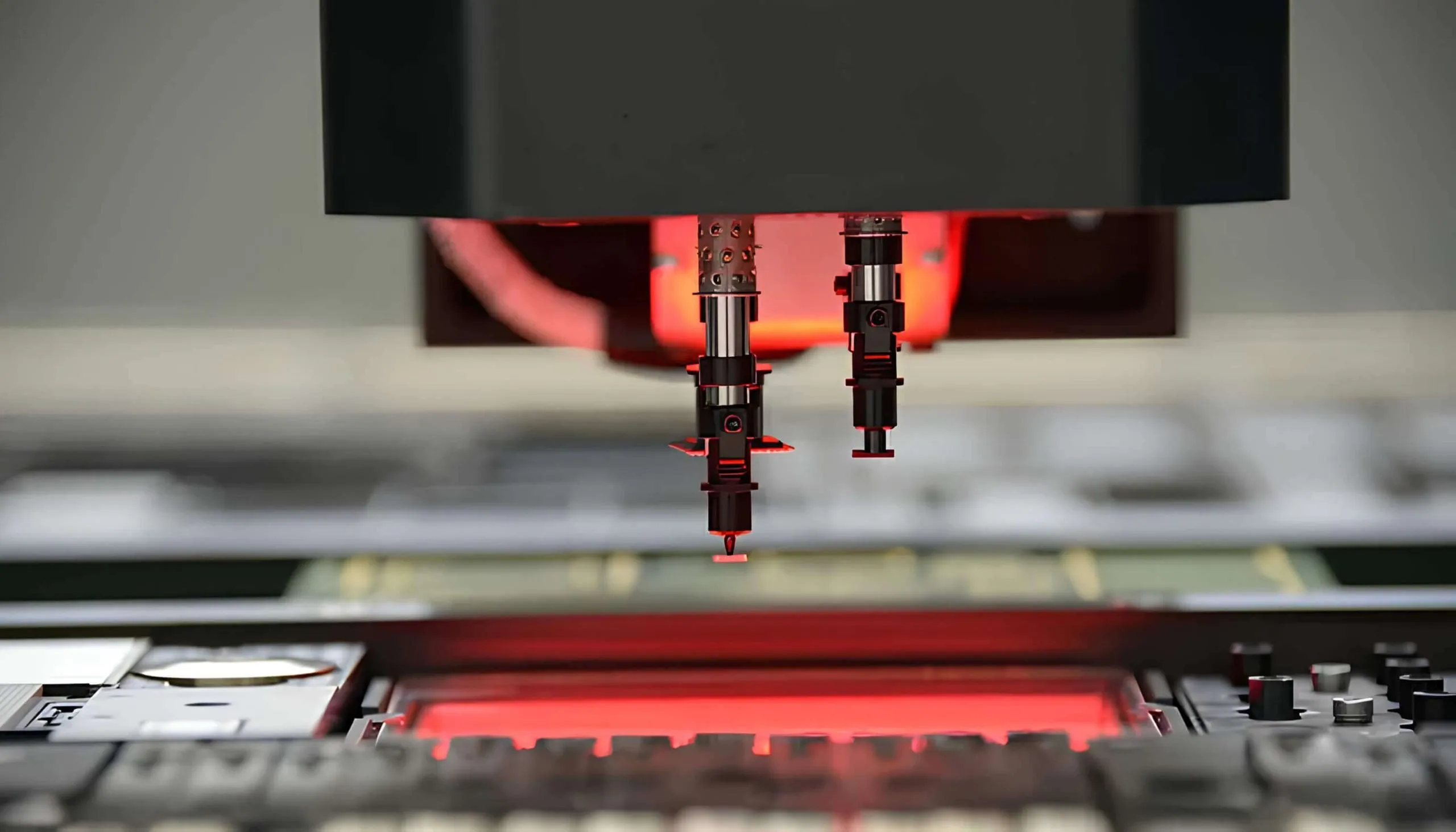
Pick and place machines operate through a sequence of coordinated steps driven by software and hardware synergy. First, the machine scans fiducial markers on the PCB for alignment, compensating for any board warp or printer offsets. Vision cameras then identify components in feeders, verifying orientation and position before pickup. The nozzle descends, applies vacuum to lift the part, rotates it if needed, and moves to the drop site over the corresponding pad.
Precision comes from high-resolution encoders on X, Y, and Z axes, often achieving placement accuracy under 50 microns. Feeders dispense components sequentially from reels, while software optimizes head paths to minimize travel time. For hobbyists, understanding feeder setup is crucial, as mismatched tape widths cause jams. Post-placement, the PCB moves to reflow soldering, where heat melts the paste to form joints.
Advanced models use dual heads or turret systems for throughput, but basics suffice for hobbyist volumes. Standards like IPC-A-610 define acceptable placement offsets, typically within 25% of pad size for most electronic components. Ignoring these leads to rework after reflow.
Preparing Your PCB for Successful Pick and Place
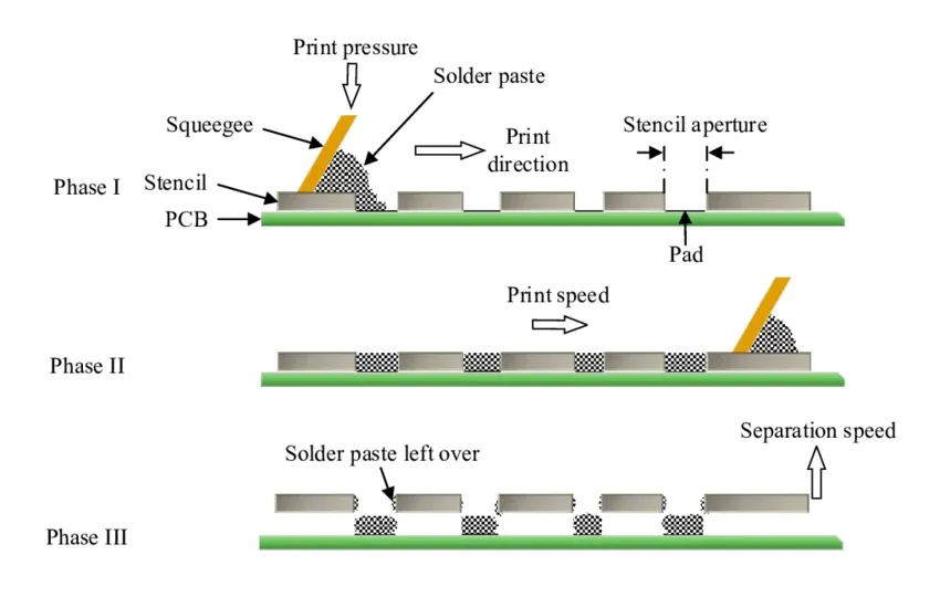
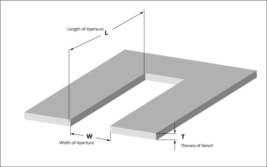
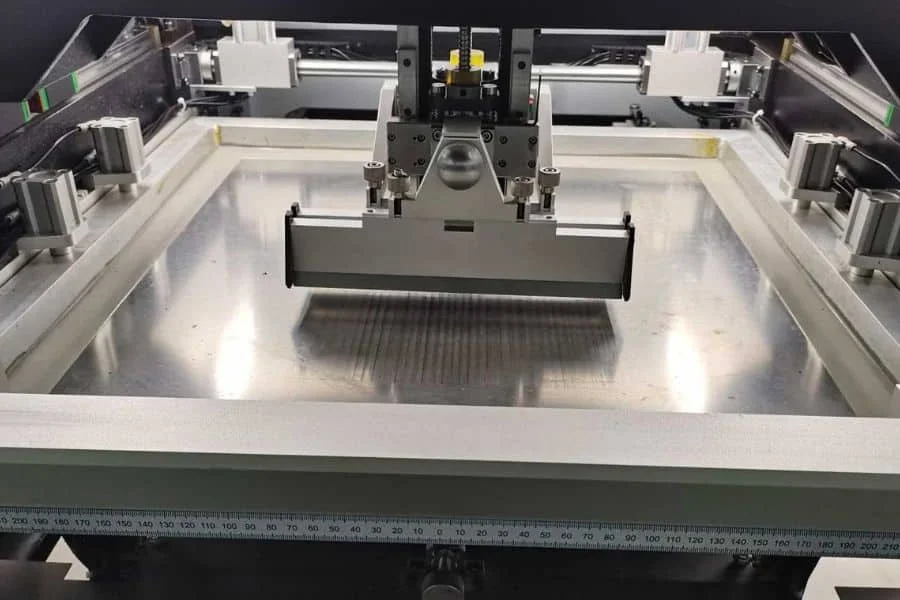
Preparation starts with solder paste printing using a stencil aligned to the PCB. Apply paste evenly on pads via a squeegee, then inspect under magnification for uniform deposits, voids, or smears. Uneven paste causes poor adhesion during placement or reflow soldering defects. Clean the stencil between prints to avoid residue buildup.
Next, generate a centroid file from your PCB design software, listing component coordinates, rotations, and sizes. Load this into the SMT machine software, mapping it to feeder slots. Verify feeder compatibility with component tapes; for example, 8mm reels for small passives. Place fiducials, small copper pads, in corners and center of the PCB for machine calibration.
Bake moisture-sensitive electronic components per their ratings to prevent popcorning in reflow. Secure the PCB on the machine pallet with clamps or vacuum hold-down. Double-check polarity for diodes and ICs, as vision systems may not always detect markings reliably.
Step-by-Step Guide to Operating a Pick and Place Machine
Power on the SMT machine and home all axes before loading. Install feeders starting with largest components to avoid collisions, securing them firmly. Input the job file, run a dry placement test without paste to simulate and spot programming errors. Adjust nozzle sizes for component heights; too small causes damage, too large drops parts.
Initiate the placement cycle, monitoring the first few boards for accuracy via the vision system. Pause if offsets exceed tolerances defined in IPC-A-610. Common adjustments include Z-height for tall parts or feeder tension for sticky components. After placement, gently transfer PCBs to the reflow oven carrier.
For multi-layer or double-sided boards, place bottom-side components first if heat warps the board. Software features like auto-optimization reduce cycle time by grouping nearby parts. Always wear ESD protection to safeguard sensitive electronic components.
Integrating Reflow Soldering After Pick and Place
Reflow soldering solidifies the assembly by heating the PCB through predefined profiles. Preheat gently to activate flux and volatilize solvents, avoiding thermal shock. Peak temperature melts solder balls, forming intermetallic bonds, then cool controlled to prevent warping.
Profile per J-STD-001 guidelines: ramp up 1-3°C/second, soak 60-120 seconds, reflow 40-90 seconds above liquidus. Use thermocouples on test boards to validate oven zones. For hobbyists, conveyor ovens or batch types work well post-pick and place.
Inspect joints visually or with AOI for bridges, insufficient solder, or head-in-pillow defects. Rework misplacements before full reflow batches.
Troubleshooting Common Issues in Pick and Place Assembly
Misalignment tops the list, often from poor fiducials or warped PCBs. Calibrate the machine with a known-good board and measure offsets. Component flipping occurs if vacuum fails; clean nozzles and check feeder alignment. Jams in feeders stem from dust or incorrect tape pitch, so preload small quantities initially.
Post-placement shifts happen during transfer to reflow; use anti-static supports. Tombstoning in reflow traces to uneven paste or cooling rates, fix by refining stencil apertures. For sticky parts in humid environments, use dry cabinets.
Log errors in machine software for pattern analysis. Consistent troubleshooting builds reliable processes.
Best Practices for Hobbyists Using SMT Machines
Organize components by type and quantity upfront to streamline feeder swaps. Test small runs before full panels to validate setup. Maintain machine cleanliness, especially optics and nozzles, with isopropyl alcohol wipes. Update software for latest algorithms improving placement speed.
Panelize PCBs with breakaway tabs for efficient handling. Source consistent electronic components to avoid feeder recalibration. Track metrics like placement speed and yield to refine over time.
Conclusion
Pick and place machines transform PCB assembly for hobbyists, enabling professional results with SMT precision. From paste application to reflow soldering, each step demands attention to detail for robust electronic components joints. By following best practices and standards like IPC-A-610 and J-STD-001, users minimize defects and maximize efficiency. Experiment iteratively, and soon complex boards will be routine. This guide equips beginners to dive into automated assembly confidently.
FAQs
Q1: What role does a pick and place machine play in PCB assembly?
A1: A pick and place machine, or SMT machine, automates placing electronic components on solder paste-coated PCBs. It ensures accuracy for fine-pitch parts, reducing manual errors before reflow soldering. Hobbyists gain speed for prototypes without sacrificing quality. Proper setup prevents common issues like misalignment.
Q2: How do I prepare electronic components for an SMT machine?
A2: Sort components by tape size and bake moisture-sensitive ones to avoid reflow defects. Load feeders sequentially, verifying pitch matches. Use the machine’s vision to confirm pickup. This prevents jams and ensures precise PCB placement.
Q3: What causes placement errors in pick and place machines?
A3: Errors stem from fiducial misalignment, dirty nozzles, or incorrect Z-height. Check calibration with test runs and clean regularly. Warped PCBs shift components during reflow soldering. Adhering to IPC-A-610 tolerances resolves most issues.
Q4: Why is reflow soldering critical after pick and place?
A4: Reflow melts solder paste, forming reliable joints for electronic components on the PCB. Follow J-STD-001 profiles to prevent defects like voids or bridges. Proper cooling preserves board integrity for functional assemblies.
References
IPC-A-610K — Acceptability of Electronic Assemblies. IPC, 2020
IPC J-STD-001H — Requirements for Soldered Electrical and Electronic Assemblies. IPC, 2017
JEDEC J-STD-020E — Moisture/Reflow Sensitivity Classification of Nonhermetic Surface Mount Devices. JEDEC, 2014