Introduction
Rigid-flex PCB assembly combines the benefits of rigid and flexible circuits, enabling compact designs for industries like aerospace, medical, and telecommunications. While FR-4 has long been the standard substrate for rigid PCBs due to its affordability and versatility, modern applications often demand advanced PCB substrates and high-performance PCB materials. These materials must withstand extreme conditions, support high-frequency signals, and ensure reliability in dynamic flexing environments. This article explores alternative PCB materials beyond FR-4, including ceramic PCB and PTFE PCB options, to address the unique challenges of rigid-flex designs. Written for electrical engineers, the content focuses on technical properties, practical applications, and industry standards to guide material selection for optimal performance.
Why Advanced Substrates Matter in Rigid-Flex PCB Assembly
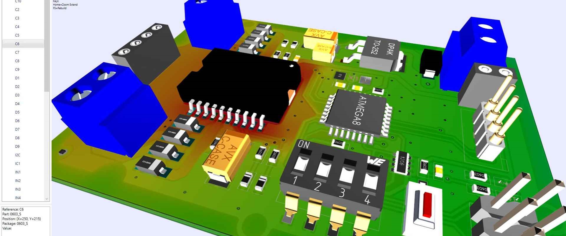
Rigid flex PCBs integrate rigid sections for component mounting with flexible sections for dynamic bending. This hybrid nature requires substrates that balance mechanical strength, thermal stability, and electrical performance. FR-4, a glass-reinforced epoxy laminate, serves well in many standard applications but falls short in high-frequency, high-temperature, or mechanically demanding scenarios. Advanced PCB substrates address these limitations by offering superior dielectric properties, thermal conductivity, and flexibility. Selecting the right high-performance PCB materials ensures signal integrity, reduces thermal stress, and enhances durability in compact, complex assemblies. For engineers, understanding these materials is critical to meeting design specifications and industry standards like IPC-6013D, which governs rigid-flex board performance.
Technical Properties of Advanced PCB Substrates
Dielectric Constant and Loss Tangent
The dielectric constant (Dk) and loss tangent (Df) of a substrate influence signal propagation and loss, especially in high-frequency applications. FR-4 typically has a Dk of around 4.5 and a higher Df, leading to signal attenuation. In contrast, PTFE PCB materials offer a lower Dk, often below 2.5, and minimal Df, making them ideal for radio frequency and microwave circuits. Ceramic PCB substrates provide even greater stability with consistent Dk values across wide temperature ranges, reducing signal distortion in harsh environments.
Thermal Conductivity and Stability
Thermal management is vital in rigid-flex designs where heat dissipation affects component lifespan. Ceramic PCB materials excel with high thermal conductivity, often exceeding 20 W/mK, compared to FR-4's modest 0.3 W/mK. This property suits power electronics and LED applications. PTFE PCB substrates, while less conductive, maintain stability at elevated temperatures, resisting deformation during soldering processes governed by standards like IPC-A-600K.
Mechanical Flexibility and Strength
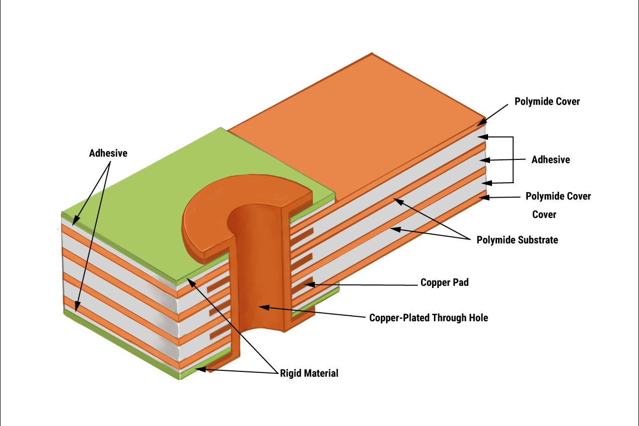
Rigid-flex assemblies endure repeated bending, requiring substrates with robust mechanical properties. Polyimide, a common flexible substrate, pairs well with advanced rigid materials in hybrid designs. Ceramic substrates, though rigid, offer exceptional hardness and resistance to vibration. Engineers must evaluate tensile strength and flex cycles to ensure compliance with IPC-6013D specifications for rigid-flex durability.
Exploring Alternative PCB Materials for Rigid-Flex Designs
Ceramic PCB Substrates
Ceramic PCB materials, such as alumina and aluminum nitride, are high-performance options for rigid sections in hybrid assemblies. They provide excellent thermal conductivity and dielectric stability, supporting high-power and high-frequency applications. While not flexible, ceramics pair effectively with polyimide in rigid-flex designs, handling heat dissipation in rigid zones. Their rigidity suits environments with minimal bending but high thermal loads, like automotive control units. However, their brittleness and higher processing costs require careful design consideration under IPC-6012E guidelines for rigid board performance.
PTFE PCB Materials
PTFE PCB substrates, known for low dielectric loss, are widely used in high-frequency rigid-flex applications. Their flexibility is limited, so they often form rigid sections combined with flexible materials. PTFE excels in microwave and RF circuits due to minimal signal loss, aligning with standards like IPC-4101E for laminate specifications. Resistance to chemicals and moisture also makes PTFE suitable for harsh environments. Engineers must account for its softer nature, which may complicate drilling and PCB assembly processes.
Polyimide and Other Flexible Alternatives
Polyimide remains the backbone of flexible sections in rigid-flex PCBs due to its high tensile strength and thermal resistance. When paired with advanced rigid substrates, it enables dynamic bending without cracking. Alternative PCB materials, such as liquid crystal polymer (LCP), offer lower moisture absorption and better high-frequency performance than polyimide. These materials meet IPC-6013D requirements for flex performance, supporting compact designs in wearable and medical devices.
Hybrid Laminates and Composites
Hybrid laminates combine different materials to balance cost and performance. For instance, pairing a low-cost rigid substrate with a high-performance flexible layer optimizes signal integrity and flexibility. Composites incorporating ceramic fillers or PTFE-based layers enhance thermal and electrical properties. Such combinations must adhere to IPC-4101E standards for material compatibility and stackup design to prevent delamination during assembly.
Practical Considerations for Selecting High-Performance PCB Materials
Application-Specific Requirements
Material selection hinges on the end application. High-frequency telecommunications demand PTFE PCB substrates for low signal loss. Aerospace applications prioritize ceramic PCB materials for thermal management and vibration resistance. Medical devices often use polyimide for flexibility in compact, biocompatible designs. Engineers must map material properties to design goals, ensuring compliance with standards like IPC-6013D for performance and reliability.
Manufacturing and Assembly Challenges
Advanced PCB substrates introduce unique fabrication challenges. Ceramic materials require specialized cutting tools due to hardness, while PTFE's soft texture complicates via formation. Rigid-flex assembly also demands precise alignment to prevent stress at transition zones. Following IPC-A-600K guidelines for board acceptability helps mitigate defects during soldering and component placement. Engineers should collaborate with fabrication teams to address material-specific handling needs.
Cost Versus Performance Trade-offs
High-performance PCB materials often carry higher costs than FR-4. Ceramic PCB substrates involve expensive raw materials and processing, while PTFE PCB options require specialized manufacturing techniques. Balancing cost with performance is essential. For less demanding applications, hybrid laminates offer a compromise by integrating cost-effective and advanced materials. Decisions must align with project budgets and long-term reliability goals.
Suggested Reading: High-Performance PCB Assembly: Key Design Considerations 2026
Best Practices for Rigid-Flex PCB Assembly with Advanced Substrates
Stackup Design Optimization
A well-planned stackup minimizes stress between rigid and flex sections. Place high-performance materials strategically to handle thermal and electrical loads. Ensure transition zones between rigid and flex layers avoid abrupt material changes, reducing delamination risks. Adhere to IPC-6013D for stackup configurations that maintain structural integrity during bending and thermal cycling.
Material Compatibility Testing
Before full-scale production, test substrate compatibility under simulated operating conditions. Evaluate thermal expansion coefficients to prevent warpage, as outlined in IPC-6012E for rigid board performance. Assess dielectric properties for high-frequency designs to confirm signal integrity. Testing ensures materials withstand assembly processes like reflow soldering without degrading.
Process Control During Assembly
Tight control over assembly parameters prevents defects with advanced PCB substrates. Monitor temperature profiles during soldering to avoid damaging heat-sensitive materials, following JEDEC J-STD-020E for moisture sensitivity. Use proper fixturing to support rigid-flex boards during component placement, minimizing mechanical stress. Consistent process monitoring aligns with IPC-A-600K standards for board quality.
Conclusion
Rigid-flex PCB assembly benefits immensely from advanced PCB substrates that surpass the limitations of traditional FR-4. High-performance PCB materials like ceramic PCB and PTFE PCB substrates offer superior thermal, electrical, and mechanical properties for demanding applications. Alternative PCB materials, including polyimide and hybrid laminates, provide flexibility and cost-effective solutions for complex designs. By understanding material properties and adhering to industry standards such as IPC-6013D and IPC-A-600K, engineers can optimize rigid-flex designs for reliability and performance. Careful selection and testing of substrates ensure successful outcomes in challenging environments.
FAQs
Q1: What are the benefits of using ceramic PCB substrates in rigid-flex designs?
A1: Ceramic PCB substrates offer high thermal conductivity and dielectric stability, making them ideal for rigid sections in rigid-flex designs. They excel in heat dissipation for power electronics and maintain signal integrity in high-frequency applications. While not flexible, ceramics pair well with materials like polyimide, ensuring reliability under thermal stress as per IPC-6012E standards. Their use enhances performance in harsh environments like automotive systems.
Q2: How do PTFE PCB materials improve high-frequency rigid-flex applications?
A2: PTFE PCB materials provide a low dielectric constant and minimal loss tangent, reducing signal attenuation in high-frequency circuits. They suit rigid sections in rigid-flex designs for telecommunications and RF applications. Their chemical resistance and thermal stability align with IPC-4101E specifications, ensuring durability. PTFE enhances performance where signal integrity is critical, though it requires careful handling during fabrication.
Q3: What alternative PCB materials can replace FR-4 in rigid-flex assembly?
A3: Alternative PCB materials like polyimide for flexible sections and hybrid laminates for rigid zones can replace FR-4. Liquid crystal polymer offers low moisture absorption and high-frequency performance. Ceramic and PTFE substrates provide thermal and electrical advantages for specific needs. These materials meet IPC-6013D requirements, supporting advanced designs in compact, high-stress applications while balancing cost and performance.
Q4: Why is stackup design critical for advanced PCB substrates in rigid-flex PCBs?
A4: Stackup design ensures compatibility between advanced PCB substrates in rigid-flex PCBs, minimizing stress at transition zones. Proper layering prevents delamination and maintains signal integrity under bending or thermal loads. It aligns high-performance materials with electrical and mechanical demands, adhering to IPC-6013D guidelines. Optimized stackups enhance reliability and performance in complex assemblies for various industries.
References
[IPC-6012E — Qualification and Performance Specification for Rigid Printed Boards. IPC, 2020.]
[IPC-6013D — Qualification and Performance Specification for Flexible and Rigid-Flex Printed Boards. IPC, 2017.]
[IPC-A-600K — Acceptability of Printed Boards. IPC, 2020.]
[IPC-4101E — Specification for Base Materials for Rigid and Multilayer Printed Boards. IPC, 2017.]
[JEDEC J-STD-020E — Moisture/Reflow Sensitivity Classification for Nonhermetic Surface Mount Devices. JEDEC, 2014.]


