Introduction
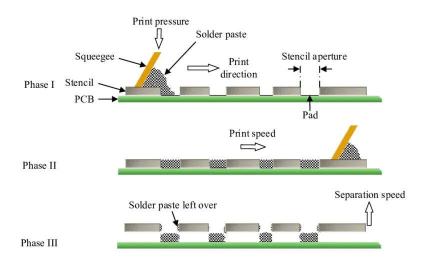
In surface mount technology assembly, the solder paste stencil plays a critical role in achieving precise solder deposit volumes on PCB pads. Engineers often default to stainless steel stencils due to their proven reliability, but emerging demands like finer pitches and higher yields push the boundaries of material selection. Choosing the right stencil material directly impacts print quality, defect rates, and overall process efficiency. This article explores stencil material comparison beyond the traditional choice, including stainless steel vs nickel stencil options, and evaluates stencil coating options for optimized performance. For electric engineers troubleshooting high-density boards, understanding these factors ensures consistent reflow soldering results without excessive rework.
Why Stencil Material Selection Matters in PCB Assembly
Stencil materials influence solder paste transfer efficiency, aperture wall quality, and longevity under repeated printing cycles. Poor material choice leads to issues like insufficient paste volume, bridging, or solder balls, especially in high-volume production. Industry standards like IPC-7525C provide guidelines for stencil design, emphasizing material properties that support uniform deposition. As component pitches shrink below 0.4 mm, engineers must prioritize materials that maintain clean release and minimize residue buildup. Ultimately, the right stencil material aligns with your PCB's pitch, paste type, and throughput requirements, reducing downtime and scrap rates.
Stainless steel dominates due to its cost-effectiveness and machinability, but it may not suffice for ultra-fine features where nickel offers superior edge definition. Coatings further extend stencil life by improving release properties. Troubleshooting common print defects often traces back to mismatched material-aperture interactions.
Stainless Steel Stencils: Reliable and Versatile
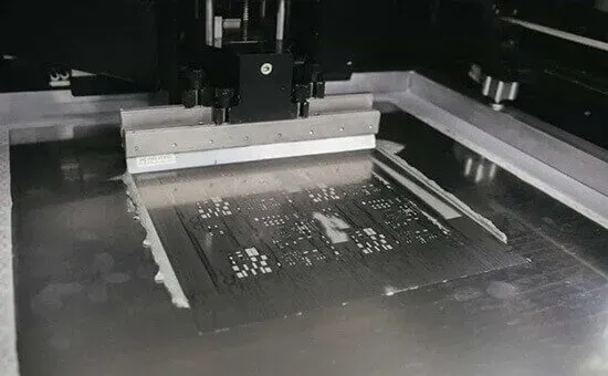
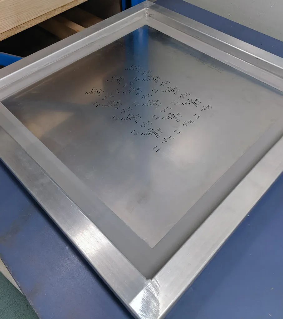
Stainless steel stencils, typically laser-cut from 304 or 316 alloys, serve as the workhorse in most SMT lines. Their thickness ranges from 100 to 150 microns, balancing paste volume for standard QFN and BGA components. Laser cutting produces trapezoidal apertures that promote good paste release after electropolishing. These stencils withstand thousands of prints with proper cleaning, making them ideal for mid-volume production. However, for pitches under 0.5 mm, stainless steel's coarser grain structure can lead to inconsistent sidewall smoothness.
Engineers appreciate stainless steel's affordability and quick turnaround, but regular inspection for wear is essential. In stencil material comparison, it excels in durability for larger apertures but lags in fine-pitch precision compared to alternatives.
Nickel Stencils: Superior for Fine Pitch Demands
Electroformed nickel stencils provide exceptional precision through a photolithographic process that yields vertical or slightly tapered walls. Available in thicknesses as low as 25 microns, they suit ultra-fine pitch components like 01005 resistors or 0.3 mm pitch BGAs. Nickel's lower coefficient of friction reduces paste adhesion, enhancing transfer efficiency over multiple cycles. This material resists abrasion better than stainless steel, minimizing aperture enlargement during extended runs. In stainless steel vs nickel stencil evaluations, nickel shines for high-reliability applications where defect rates must stay below 1%.
Fabrication involves electroplating onto a photoresist-patterned mandrel, ensuring sub-micron tolerances. While costlier upfront, nickel stencils lower overall ownership costs by cutting rework in fine-pitch assemblies.
Stencil Material Comparison: Key Properties Side-by-Side
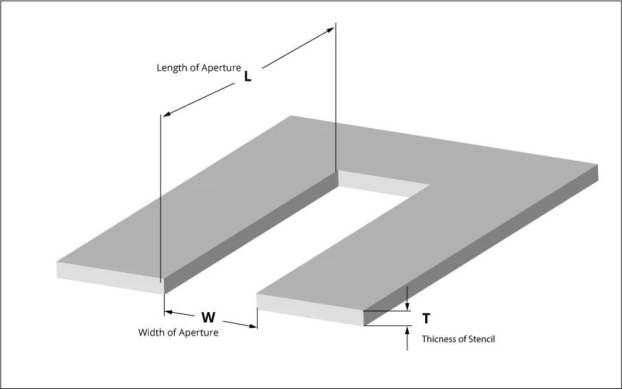
When conducting a stencil material comparison, engineers evaluate factors like fabrication method, aperture quality, durability, cost, and suitability for pitch. Stainless steel offers broad versatility with laser cutting speeds up to 1000 apertures per minute, while nickel's electroforming delivers smoother surfaces ideal for Type 5 solder pastes. Here's a practical breakdown:
- Typical Thickness — Stainless Steel: 100–150 μm; Electroformed Nickel: 25–125 μm
- Aperture Walls — Stainless Steel: Trapezoidal, electropolished; Electroformed Nickel: Vertical, inherently smooth
- Fine Pitch Suitability — Stainless Steel: Good up to 0.5 mm; Electroformed Nickel: Excellent below 0.4 mm
- Durability (Prints) — Stainless Steel: 50,000+ with maintenance; Electroformed Nickel: 100,000+ due to hardness
- Cost — Stainless Steel: Lower; Electroformed Nickel: Higher
- Best For — Stainless Steel: Standard SMT, cost-sensitive; Electroformed Nickel: High-density, precision
This breakdown highlights trade-offs: stainless steel for volume, nickel for precision. IPC-7527 outlines solder paste printing requirements that both materials can meet when properly finished.
Stencil Coating Options: Boosting Release and Longevity
Stencil coating options address common pain points like paste residue and inconsistent release. Electropolishing remains standard for stainless steel, reducing surface roughness to under 0.5 μm for better cleanability. Advanced nano-coatings form a hydrophobic layer on aperture walls, repelling flux and particles. These treatments extend cleaning intervals from every 10 prints to 50 or more, critical in high-throughput lines. For nickel stencils, coatings enhance already smooth surfaces without compromising precision.
Choosing coatings depends on paste chemistry and environmental factors like humidity. Troubleshooting sticky paste often resolves with a fresh nano-coat application.
NanoProTek Coating Benefits: A Closer Look
NanoProTek coating benefits include dramatically improved solder paste release, particularly for low-area-ratio apertures common in fine-pitch designs. This oleophobic nano-layer prevents flux from wetting walls, reducing bridging and solder balling defects by up to 50% in tests. It also minimizes cleaning frequency, boosting uptime in automated printers. Applied via wipe or spray, NanoProTek withstands thousands of cycles without degradation, making it cost-effective for production stencils. Engineers report consistent transfer efficiencies above 90% even after 10,000 prints.
In stencil coating options, NanoProTek stands out for its compatibility with Type 4 and Type 5 pastes, aligning with IPC-7525C guidelines for fine-pitch printing. Pair it with nickel for optimal results on 0.25 mm pitches. [8][9][10]
Stencil Material for Fine Pitch: Strategic Selection
For stencil material for fine pitch components under 0.4 mm, nickel electroforms dominate due to their ability to hold 50 μm apertures without bridging. Thinner stencils (75–100 μm) paired with nano-coatings ensure adequate volume without excess height. Stainless steel works if laser-optimized with hybrid cutting, but risks higher defect rates on 01005 parts. Test prints validate choices: aim for 75–125% transfer efficiency per IPC-7527 criteria. Factor in board warpage and pad coplanarity during selection.
Practical tip: Start with stencil thickness at 120% of smallest pitch for balanced deposits.
Best Practices and Troubleshooting for Stencil Success
Select materials based on area ratio (aperture area to wall area): below 0.66 favors nickel or coated stainless. Maintain stencil tension at 20–25 N/cm for frameless types to prevent deflection. Clean with low-pressure vacuums per IPC-7526A to preserve coatings. Troubleshoot insufficient deposits by checking squeegee pressure (1–2 kg/cm) and speed (20–50 mm/s). For bridging, refine aperture reductions to 5–10% per IPC-7525C. Document print parameters to correlate material performance with yields.
Regular profilometry verifies aperture integrity after 5,000 cycles. Hybrid stencils combining stainless frames with nickel foils offer flexibility for step designs.
Conclusion
Moving beyond stainless steel unlocks superior performance in demanding SMT applications through targeted stencil material comparison. Nickel excels in stainless steel vs nickel stencil scenarios for fine pitch, while stencil coating options like NanoProTek amplify benefits across materials. Electric engineers gain reliability by matching material to pitch, paste, and process needs, guided by standards like IPC-7525C and IPC-7527. Implement these insights to minimize defects, extend stencil life, and streamline assembly.
FAQs
Q1: What is the best stencil material for fine pitch components under 0.4 mm?
A1: Nickel electroformed stencils provide the stencil material for fine pitch needs due to vertical walls and low friction, achieving high transfer efficiency. Stainless steel suffices with coatings but may require more frequent cleaning. Follow IPC-7525C for aperture sizing to avoid bridging. Test with your paste for optimal thickness around 75 μm.
Q2: How does stainless steel vs nickel stencil impact print quality?
A2: In stainless steel vs nickel stencil comparison, nickel offers smoother release for consistent volumes in high-density boards, reducing solder balls. Stainless steel handles standard pitches economically but shows wear faster on fine features. Coatings can narrow the gap; measure yields post-reflow to decide.
Q3: What are key stencil coating options and their advantages?
A3: Stencil coating options include electropolishing for basic smoothness and nano-coatings for flux repulsion. They cut cleaning cycles and boost efficiency for Type 5 pastes. NanoProTek coating benefits feature defect reduction in low-ratio apertures, ideal for production.
Q4: When should I consider NanoProTek for my stencil?
A4: Opt for NanoProTek coating benefits in fine-pitch or high-volume runs to enhance paste release and durability. It excels with nickel stencils, minimizing rework on 01005 components. Apply before first use and monitor via SPI for sustained 90%+ transfers.
References
[IPC-7525C — Stencil Design Guidelines. IPC, 2021]
[IPC-7527 — Requirements for Solder Paste Printing. IPC]
[IPC-7526A — Stencil and Misprinted Board Cleaning Handbook. IPC, 2022]