Introduction
In the world of electronic hobbyists, creating custom circuit boards opens up endless possibilities for prototyping and small-scale production. A DIY pick and place machine brings automation to your workbench, allowing precise placement of surface-mount components without manual fatigue. This project combines 3D printed electronics with affordable hardware, making it accessible for anyone passionate about building their own tools. By constructing a mini version, you gain hands-on experience in mechatronics while speeding up assembly for your custom circuit boards. Whether you're populating boards for IoT gadgets or audio projects, this machine transforms hobbyist workflows. Let's dive into how to build one step by step.
What Is a Pick and Place Machine and Why Build Your Own?
A pick and place machine automates the process of picking small electronic components from feeders and placing them accurately onto a PCB stencil or bare board. In professional SMT lines, these machines handle thousands of parts per hour with micron-level precision, but for hobbyists, a mini version focuses on batches of 10 to 100 components. Building a DIY pick and place saves thousands compared to commercial units, empowers customization, and teaches core principles of robotics and control systems. It's particularly valuable for 3D printed electronics projects where you iterate on custom circuit boards frequently. Hobbyists often face limitations with hand placement, like misalignment or eye strain, which this machine eliminates. Embracing this build aligns with the growing maker movement, where open-source designs democratize advanced manufacturing.
The relevance extends to producing reliable prototypes that mimic production quality. Adhering to standards like IPC-A-610 helps ensure your placed components meet acceptability criteria for electronic assemblies, even in a DIY setup. This not only boosts confidence in your custom circuit boards but also prepares you for scaling to semi-professional levels.
Core Technical Principles Behind a Mini Pick and Place
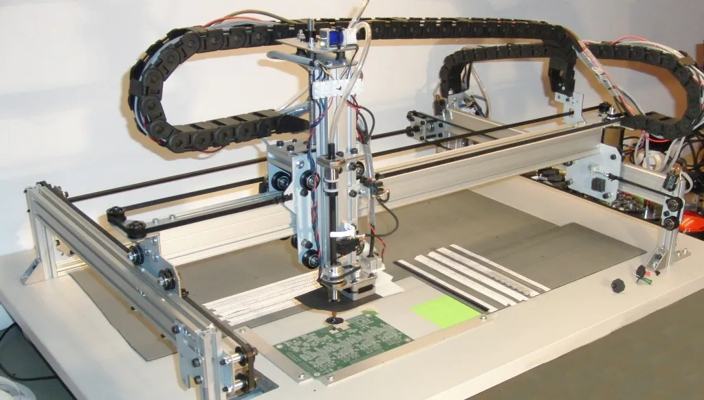
At its heart, a pick and place machine relies on a Cartesian coordinate system for motion, using X, Y, and Z axes to navigate the workspace. Stepper motors drive belts or lead screws to achieve repeatable positioning, typically aiming for 0.1mm accuracy suitable for hobbyist SMD parts like 0805 resistors or SOIC chips. A vacuum nozzle serves as the end effector, lifting components via suction generated by a small pump, while a vision system—often a webcam—identifies part orientation and corrects for offsets. Control logic, powered by a microcontroller like an Arduino or Raspberry Pi, orchestrates the sequence: pick from feeder, scan, rotate if needed, and place on the board fiducials. Software fiducials and nozzle calibration ensure alignment with PCB pads, preventing defects like tombstoning during reflow.
Feeder mechanisms are simplified in DIY designs, using tape reels or vibration bowls to present parts sequentially. Precision hinges on minimizing backlash in the mechanical drivetrain and stable Z-axis descent to avoid damaging delicate leads. Electrical noise from motors can interfere with vision processing, so shielding and decoupling capacitors are essential. For hobbyists venturing into 3D printed electronics, printing lightweight gantry parts reduces inertia, allowing faster moves without sacrificing accuracy.
Understanding tolerances is key; component placement must align within pad dimensions to comply with J-STD-001 requirements for soldered electrical assemblies. This standard guides spacing and offset limits, ensuring your DIY pick and place produces boards ready for reliable reflow soldering.
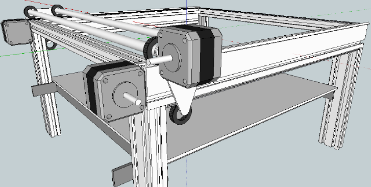
Designing and Building the Mechanical Structure
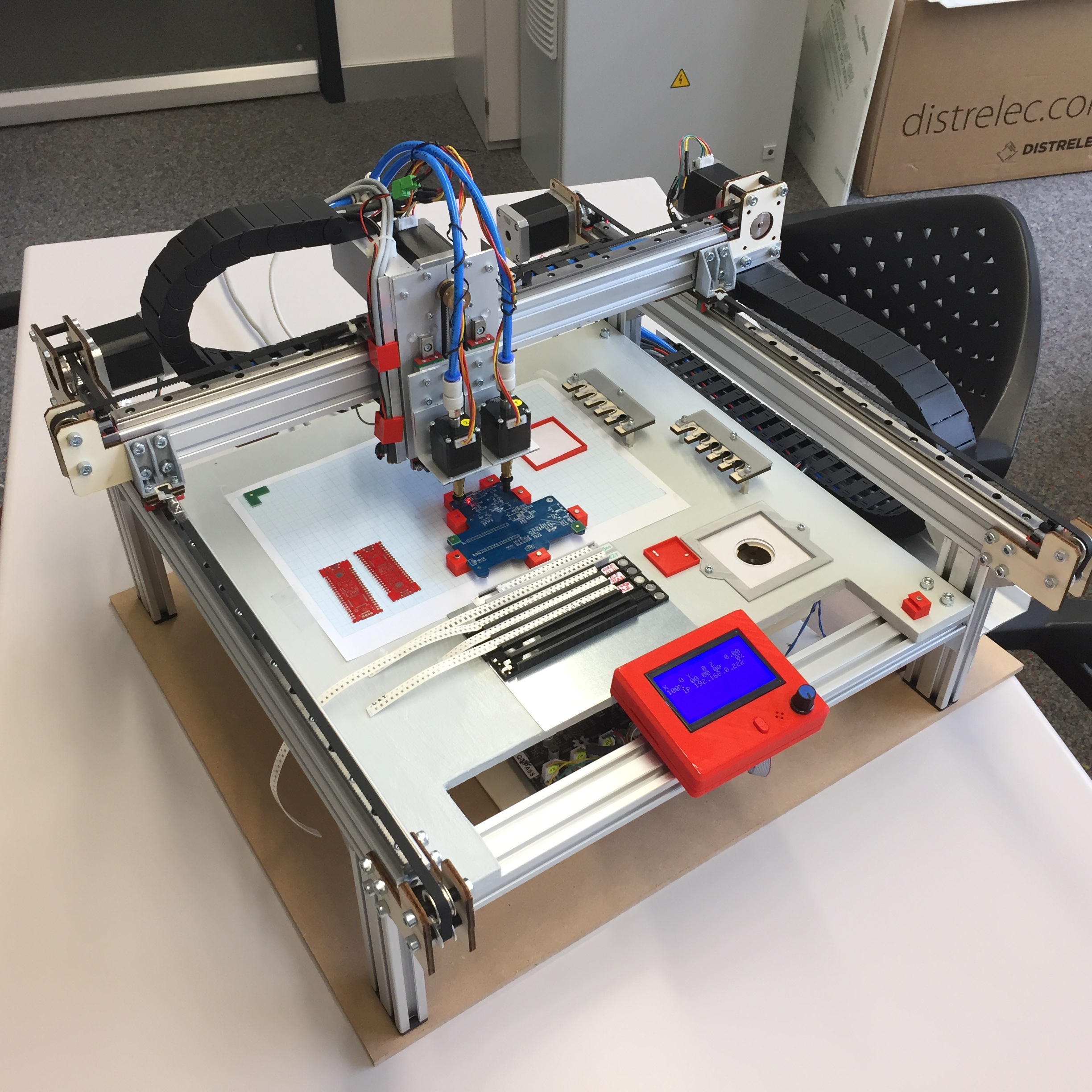
Start with a sturdy frame, ideally 3D printed from ABS or PETG for rigidity and ease of iteration. Design a gantry-style structure around 300mm x 300mm x 100mm to handle standard maker PCBs up to 200mm square. Core components include NEMA 17 stepper motors for each axis, GT2 timing belts for X and Y, and a trapezoidal lead screw for Z-motion. Mount linear rods or rails to guide smooth travel, and integrate endstops for homing. The print bed or PCB holder should use adjustable clamps and fiducial markers for repeatable positioning. Assemble with M3 screws and printed brackets, testing for squareness with a machinist's square.
Next, engineer the pickup head: a 12V vacuum solenoid valve connected to silicone tubing and interchangeable nozzles sized for 0402 to QFN packages. Add a rotary stage using a servo for theta alignment, driven by vision feedback. Power everything via a 12V/24V supply with buck converters for logic levels. Cable management prevents snags during operation, using drag chains or ties.
Implementing the Vision and Control System
Vision is the brain of your DIY pick and place, using OpenCV on a Raspberry Pi to detect blobs and contours. Calibrate the camera above the nozzle, capturing images at fixed heights to compute offsets via fiducial patterns printed on the PCB. Process parts by thresholding for contrast, then apply rotation matrices for alignment. Feeders can be simple motorized spools advancing tape via another stepper.
Software ties it together: generate a bill-of-materials file in CSV with XY positions exported from your PCB design tool. A Python script parses this, commands motors via GPIO or GRBL shield, and loops through placements. Tune acceleration profiles to avoid overshoot, starting at 1000mm/min speeds for hobbyist throughput of 50-100 parts per hour.
Safety features like emergency stops and enclosure interlocks prevent mishaps. For quality, verify placements against IPC-A-610 class 2 criteria, targeting no more than 50 micron offsets for fine-pitch parts.
Practical Best Practices for Assembly and Operation
Source components from electronics suppliers, prioritizing matched stepper drivers like TMC2209 for quiet, precise steps. 3D print prototypes iteratively, using slicer supports for overhangs in nozzle holders. Assemble on a vibration-dampening surface to maintain accuracy during runs.
Calibrate religiously: home axes, level the bed, and run test patterns with dummy components. Troubleshoot vacuum issues by checking seals and pump pressure, aiming for 0.5-0.8 bar hold. For custom circuit boards, bake out moisture per JEDEC J-STD-020 guidelines before placement to avoid popcorn effects in reflow.
Optimize feeders for common parts; tape width standardization simplifies swaps. Run dry cycles first to debug paths. Maintain with lubrication on rods and belt tension checks.
Common Troubleshooting and Optimization Tips
Hobbyists often encounter placement inaccuracies from belt stretch or thermal expansion in 3D printed parts. Counter this by tensioning belts firmly and using enclosures for temperature stability. Vision failures stem from poor lighting; add ring LEDs for consistent illumination.
Motor skips happen under load; reduce speeds or upgrade to higher-torque motors. Nozzle jams require quick-swap designs and part orientation in feeders. For reflow prep, inspect placements visually and with continuity tests.
Scale up by adding multiple nozzles or larger beds, but start simple. Community-shared configs accelerate learning without trial-and-error pitfalls.
Conclusion
Building a mini pick and place machine empowers electronic hobbyists to automate custom circuit board assembly with professional results. From 3D printed frames to vision-guided precision, this DIY project blends mechanics, software, and electronics into a rewarding tool. Following best practices and standards ensures reliable outcomes, reducing defects and boosting productivity. Whether for prototypes or small runs, it unlocks creativity in 3D printed electronics. Start small, iterate, and watch your workbench evolve into a mini factory.
FAQs
Q1: What materials do I need for a basic DIY pick and place machine?
A1: You'll need 3D printed parts for the frame, NEMA 17 steppers, GT2 belts, a vacuum pump, Raspberry Pi for control, and a USB camera. Focus on affordable off-the-shelf items to keep costs under a few hundred dollars. This setup handles most SMD for custom circuit boards. Test compatibility early for smooth integration.
Q2: How accurate can a hobbyist DIY pick and place be?
A2: Expect 0.1mm to 0.2mm placement accuracy with proper calibration, sufficient for 0805 parts and larger on custom circuit boards. Finer pitches need vision tweaks and rigid mechanics. Align with IPC-A-610 for acceptable offsets. Regular homing prevents drift.
Q3: Can I use this machine for 3D printed electronics projects?
A3: Yes, it's ideal for populating boards in 3D printed enclosures or wearables. The compact size fits maker spaces, and software flexibility supports varied layouts. Ensure feeders match your SMD tapes. Bake boards pre-placement per standards for reflow success.
Q4: What software works best for controlling a DIY pick and place?
A4: Open-source Python with OpenCV handles vision and GRBL for motion. Parse Gerber or CSV files from your design software. Customize for feeders and speeds. This combo excels in DIY pick and place for hobbyists. Debug iteratively for reliability.
References
[IPC-A-610H — Acceptability of Electronic Assemblies. IPC, 2019]
[J-STD-001H — Requirements for Soldered Electrical and Electronic Assemblies. IPC/JEDEC, 2018]
[JEDEC J-STD-020E — Moisture/Reflow Sensitivity Classification of Nonhermetic Solid State Surface Mount Devices. JEDEC, 2014]


