Introduction
After assembling a PCB prototype, protecting it from environmental threats becomes crucial for reliable performance during testing and early validation. Flux residues, solder particles, and handling contaminants left behind can lead to issues like corrosion, electrical shorts, or dendrite growth over time. Cleaning removes these risks effectively, while conformal coating adds a barrier against moisture, dust, and chemicals. For electric engineers working on prototypes, mastering PCB cleaning methods and conformal coating application ensures prototype durability in real-world simulations. This article explores practical steps, troubleshooting tips, and best practices to safeguard your assemblies without compromising functionality. Proper post-assembly care aligns with industry expectations for robust electronics.
Why Cleaning and Coating Matter After PCB Assembly
Post-assembly contaminants such as activated flux residues promote ionic migration under humidity, potentially causing leakage currents or failures in high-impedance circuits. Without thorough cleaning, these residues trap moisture, accelerating corrosion prevention challenges on exposed copper and solder joints. Conformal coating then seals the board, providing moisture protection for electronics in humid or harsh test environments. Engineers often overlook how unclean boards degrade prototype durability, leading to false test failures mistaken for design flaws. Implementing both steps extends the lifespan of prototypes through accelerated life testing. Standards like IPC-J-STD-001 outline cleanliness requirements to verify assembly readiness for protection layers.
Flux types vary in cleanability; no-clean fluxes minimize residues but may still require verification for sensitive applications. Coating without prior cleaning risks poor adhesion, bubbling, or pinholes that undermine corrosion prevention. In prototype phases, where iterations are frequent, quick yet effective processes prevent rework delays. Troubleshooting early contamination saves time compared to diagnosing field-like failures later. Balancing cost and thoroughness is key for electric engineers iterating designs.
Essential PCB Cleaning Methods for Prototypes
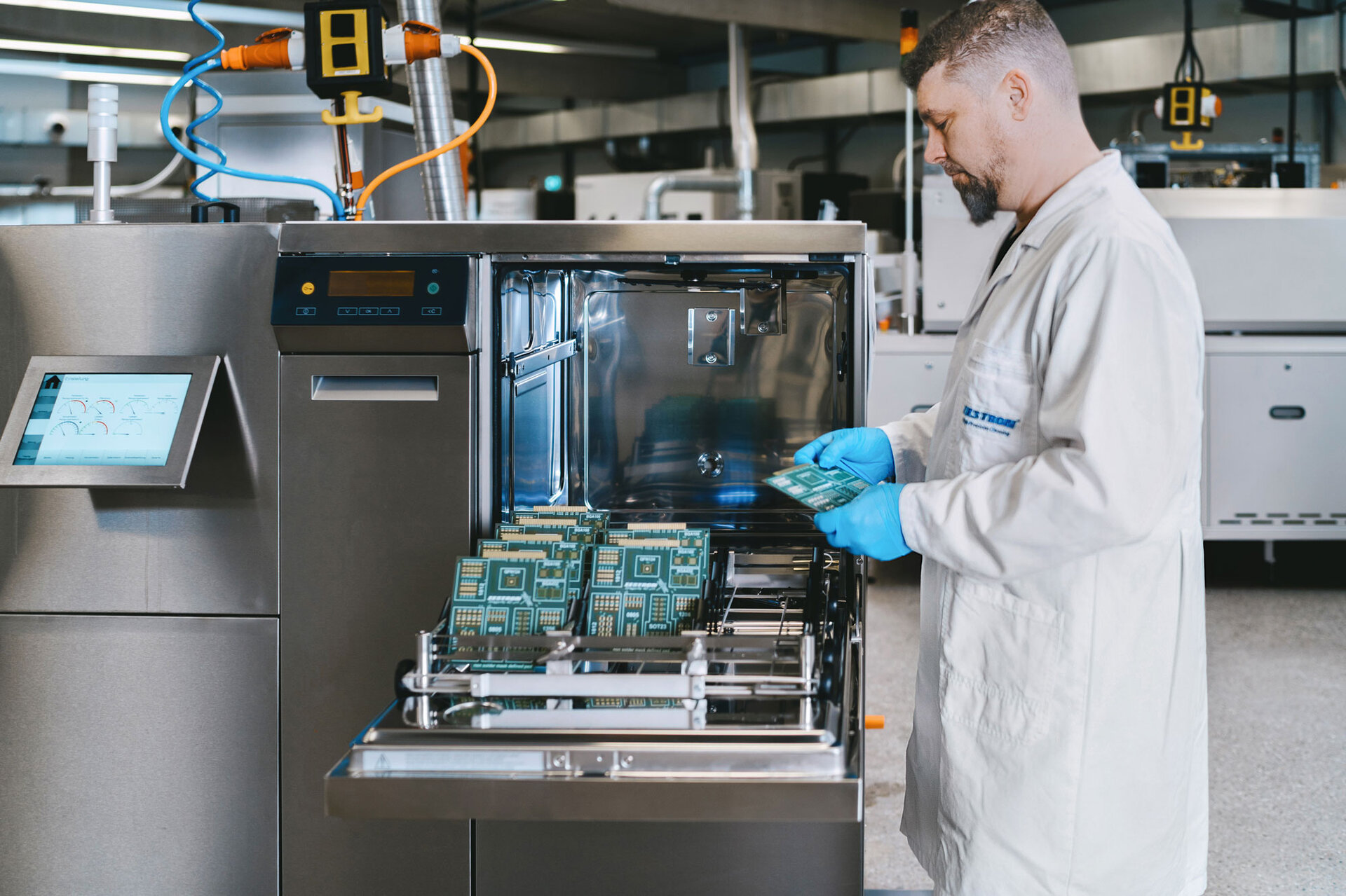
Selecting the right PCB cleaning methods depends on flux chemistry, board complexity, and component sensitivity. Solvent-based cleaning uses isopropyl alcohol or hydrocarbon solvents in vapor degreasers to dissolve organic residues quickly without water exposure. This method suits prototypes with sealed components, as it evaporates cleanly and leaves no rinse residue. Aqueous cleaning employs deionized water with alkaline or neutral detergents in spray-in-air or immersion systems, followed by thorough rinsing to achieve low ionic levels. Ultrasonic agitation enhances removal of stubborn particles from under components, but engineers must control parameters to avoid damage to delicate parts.
For no-clean processes, verifying cleanliness via resistivity of solvent extract (ROSE) testing confirms if additional steps are needed. Plasma cleaning offers a dry, residue-free option using oxygen or argon plasma to break down organics at the molecular level, ideal for prototypes heading straight to coating. Semi-aqueous methods blend solvents with water for balanced efficacy on mixed residues. Troubleshooting incomplete cleaning involves visual inspection under UV light for fluorescence and ion chromatography for halide quantification. Always dry boards completely with forced air or vacuum to prevent water spots that could initiate corrosion.
Engineers should match cleaning to assembly specifics; for example, low-residue fluxes may only need manual wiping, while high-activation types demand full immersion. Over-cleaning risks removing beneficial flux activators or damaging reflowed joints, so process qualification is essential. Prototype durability improves when cleaning reduces surface insulation resistance failures in humidity bias testing.
Preparing for Conformal Coating Application
Cleanliness verification precedes conformal coating application to ensure adhesion and void-free coverage. Mask areas like connectors and test points with tape or fixtures to prevent coating ingress, which could complicate prototyping. Surface activation via light abrasion or plasma enhances bonding without altering board geometry. Common coating types include acrylic for flexibility, silicone for high-temperature tolerance, urethane for abrasion resistance, and parylene for pinhole-free uniformity via vapor deposition.
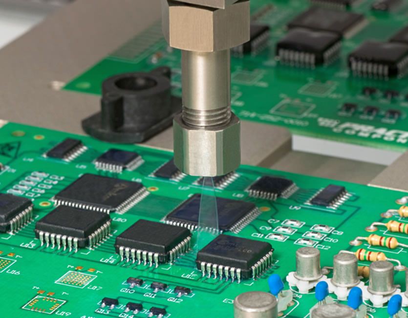
Application techniques range from selective robotic spraying for precision on prototypes to dip coating for full coverage on simple boards. Spray methods control thickness at 25 to 75 microns per pass, building layers as needed while minimizing overspray. Brush-on suits spot repairs or low-volume prototypes, though uniformity demands skill. Curing varies: room-temperature dry for acrylics, thermal bake for epoxies, or UV for fast turnaround. Per IPC-CC-830, coatings must pass dielectric withstand, moisture resistance, and thermal shock tests for qualification.
Troubleshooting adhesion failures often traces to oils or residues; re-clean with IPA wipes if needed. Thickness gauging with eddy current or beta gauges ensures compliance, as undercoating fails protection while overcoating stresses components.
Achieving Moisture Protection for Electronics and Corrosion Prevention
Conformal coatings repel moisture ingress, preventing electrolytic corrosion on intermetallic compounds at solder joints. Silicone types excel in condensing humidity, forming hydrophobic barriers that bead water away from critical paths. Urethane coatings provide robust corrosion prevention in salt-laden atmospheres, common in prototype environmental chambers. Parylene infiltrates tight spaces, offering superior dielectric strength over 1000 volts per mil.
Moisture protection for electronics extends to fungal growth inhibition, where fungicidal additives in acrylics safeguard long-term storage. Corrosion prevention mechanisms include passivating metal surfaces and sealing dendrites from propagation. In prototypes, coatings mitigate handling-induced oxidation during bench testing. Testing via salt fog chambers per ASTM B117 validates performance, revealing pinholes early.
Combined with cleaning, these layers boost prototype durability against thermal cycling and vibration. Engineers troubleshoot delamination by optimizing cure profiles and humidity control during application.
Best Practices and Troubleshooting for Prototype Durability
Integrate cleaning and coating into prototype workflow by qualifying processes with process control coupons mimicking production boards. Document cleaning efficacy with SIR testing under 85% RH and 85°C bias to predict field reliability. For conformal coating, maintain viscosity and temperature logs to ensure repeatable thickness. Avoid common pitfalls like coating over uncured solder paste remnants, which cause cracking; always reflow fully first.
Storage post-coating in dry nitrogen cabinets preserves integrity until deployment. Rework challenges, such as coating removal for component changes, use laser ablation or chemical strippers per IPC guidelines. Prototype durability testing includes thermal shock from -40°C to 125°C to verify adhesion. Scaling to production involves validating no-clean compatibility with coatings.
Conclusion
Effective PCB cleaning methods paired with precise conformal coating application form the cornerstone of post-assembly protection for prototypes. By removing residues and sealing against environmental assaults, engineers enhance moisture protection for electronics and corrosion prevention. Prototype durability rises, enabling confident design validation and fewer iterations. Adhering to practical steps and standards like IPC-A-610 ensures assemblies meet performance thresholds. Prioritize process verification and troubleshooting to deliver reliable prototypes ready for the next phase.
FAQs
Q1: What are the most effective PCB cleaning methods for removing flux after prototype assembly?
A1: For prototypes, aqueous ultrasonic cleaning excels at dislodging flux under components, using DI water rinses to minimize ions. Solvent vapor degreasing suits quick turnaround with no-clean fluxes, while plasma handles organics without liquids. Verify with ROSE testing targeting under 1.5 μg/cm2 NaCl equivalence per IPC-J-STD-001. This prevents corrosion and prepares for conformal coating application.
Q2: How does conformal coating application improve moisture protection for electronics in prototypes?
A2: Conformal coating creates a hydrophobic barrier, repelling water and inhibiting electrolytic paths on traces. Apply via spray at 50 microns for optimal dielectric strength, curing fully to avoid pinholes. It enhances prototype durability in humid tests, reducing failures from dendrite growth. Mask selectively to maintain testability.
Q3: Why is corrosion prevention critical after PCB cleaning, and how to test it?
A3: Post-cleaning residues accelerate corrosion via ion migration; thorough rinsing ensures low halides. Conformal coatings seal joints, tested via SIR under bias and humidity. Salt fog exposure reveals weaknesses early. This boosts prototype durability for electric engineers simulating field conditions.
Q4: Can no-clean fluxes skip PCB cleaning before conformal coating?
A4: No-clean fluxes often suffice if SIR passes IPC-J-STD-001 thresholds, but verify for high-reliability prototypes. Residual activators may bloom under coating, causing adhesion issues. Spot-clean suspicious areas and inspect under UV. This maintains corrosion prevention without full cleaning.
References
IPC-J-STD-001H — Requirements for Soldered Electrical and Electronic Assemblies. IPC, 2020
IPC-CC-830C — Qualification and Performance of Electrical Insulating Compounds for Conformal Coatings. IPC, 2019
IPC-A-610H — Acceptability of Electronic Assemblies. IPC, 2019


