Introduction
The SMT pick and place process forms a critical stage in surface mount technology assembly, where automated machines precisely position electronic components onto solder paste-deposited pads on the PCB. Errors during this phase can cascade into major defects, such as poor solder joints, missing components, and overall assembly failures that compromise product reliability. Electrical engineers often encounter these issues in high-volume production, where even minor deviations amplify costs through rework and yield losses. Common pitfalls include bad nozzle selection, inaccurate component placement, and problems stemming from component quality. Addressing these mistakes requires a deep understanding of machine calibration, feeder systems, and material handling to ensure consistent performance. By troubleshooting these areas systematically, teams can achieve higher first-pass yields and meet stringent quality benchmarks.
Understanding the SMT Pick and Place Process and Its Importance
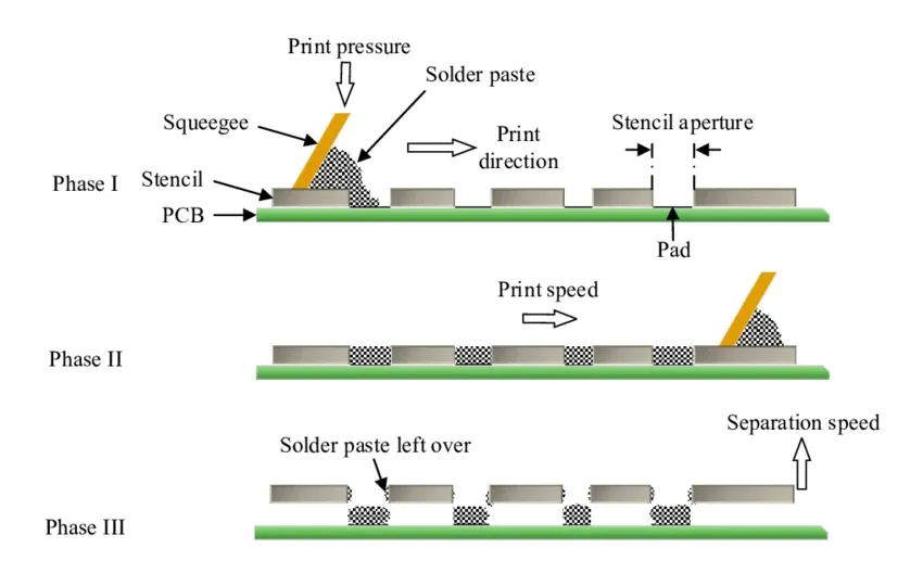
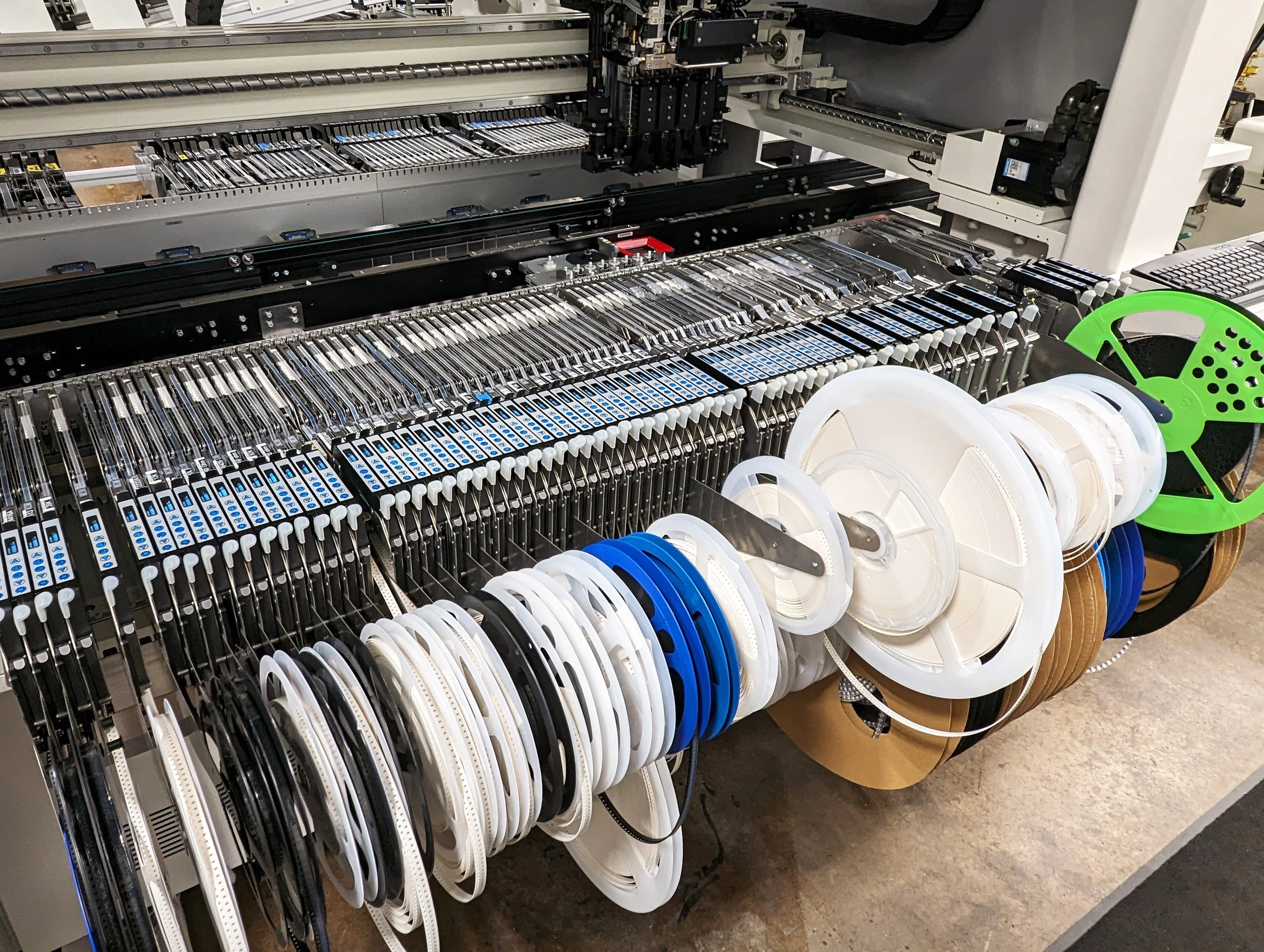
In the SMT workflow, pick and place follows solder paste printing and precedes reflow soldering, involving robotic arms that retrieve components from tape-and-reel feeders or trays using vacuum nozzles. The machine employs vision systems to align fiducials on the PCB and components, ensuring placement accuracy down to microns for fine-pitch devices. This process demands synchronization of speed, pressure, and positioning to avoid disturbances to the delicate solder paste deposits. For electrical engineers designing dense boards, precision here directly influences signal integrity and thermal performance in the final assembly. Mistakes not only lead to immediate rejects but also latent failures under vibration or thermal cycling. Mastering it aligns with industry standards like IPC-A-610, which defines acceptability criteria for electronic assemblies.
Key Causes of Common Mistakes in Component Placement
Component placement errors often arise from mechanical tolerances, software misconfigurations, or environmental factors, resulting in offsets that exceed acceptable limits. When components land off-center or rotated, they fail to align properly with pads, leading to uneven solder wetting during reflow and poor solder joints. Vision system inaccuracies, such as dirty lenses or poor lighting, exacerbate this by misreading fiducials, causing global shifts across the board. Engineers must verify machine repeatability through calibration routines, as cumulative errors from multiple heads compound over high-speed runs. Board warpage can also tilt components, mimicking placement faults while actually stemming from upstream lamination issues. These mechanisms highlight why component placement remains a top keyword in SMT troubleshooting discussions.
Poor solder outcomes frequently trace back to these placement inaccuracies, where shifted parts create voids or bridges in the reflow stage. Insufficient pad-to-component overlap reduces capillary action, starving joints of solder volume and promoting weak mechanical bonds. In high-density designs, even 50-micron offsets can trigger inspection rejects under automated optical systems. Troubleshooting involves mapping defect patterns to isolate whether the issue is systematic, like axis backlash, or sporadic, from vibration. Regular fiducial checks and height mapping prevent such drifts, ensuring compliance with placement tolerances outlined in IPC J-STD-001 for soldered assemblies.
Bad Nozzle Selection and Its Impact on Pick Reliability
Bad nozzle selection tops the list of preventable errors, as mismatched sizes or materials fail to secure components reliably during transfer. Nozzles too large for small chips cause slippage, while undersized ones deform leads on larger packages like QFNs, leading to pick failures or damage. Worn nozzles develop cracks or residue buildup, reducing vacuum efficiency and dropping components mid-flight, which contaminates the paste and necessitates cleaning halts. Engineers should match nozzle tip geometry to component profiles, considering factors like lead coplanarity and package flatness. Over time, ceramic nozzles outperform plastic in abrasive environments, but all require periodic inspection for wear indicators like pitting. This mistake directly contributes to missing components and elevates scrap rates in production.
Vacuum inconsistencies from poor nozzles also provoke tombstoning in reflow, where uneven forces lift one end of passives due to inadequate initial hold-down. Selection criteria include orifice diameter matching component bottom area for optimal suction without crushing. In practice, running nozzle tip offsets through test cycles reveals mismatches before full runs. Ignoring these leads to frequent stops, eroding throughput on high-mix lines. Proper documentation of nozzle libraries per feeder type streamlines changeovers and minimizes errors.
Missing Components: Feeder and Vision System Failures
Missing components disrupt assembly flow, often signaling feeder jams, empty reels, or vision rejects that halt the line without operator notice. Tape peel issues from improper tension cause partial picks, where leads snag and leave bodies behind, scattering debris across the board. Vision algorithms may erroneously flag good parts due to glare on shiny terminations or shadows from tall profiles, triggering unnecessary skips. Engineers troubleshoot by auditing feeder pitch settings against component specs and cleaning cameras to restore contrast thresholds. Splice detection failures during reel changes compound this, as undetected breaks load incorrect parts downstream. These incidents not only cause open joints but also risk head crashes from unhandled voids.
Advanced machines log error codes for patterns, such as repeated misses on specific feeders pointing to vacuum leaks. Implementing pre-run verification with fiducial-plus-sample checks catches 90% of setups early. Component quality plays a role here too, as bent leads or foreign matter block reliable extraction.
Component Quality Issues Leading to Process Disruptions
Component quality directly affects pick and place success, with defects like delamination or oxidation hindering vacuum pickup and alignment. Moisture-sensitive devices baked improperly per JEDEC J-STD-020 pop during handling, creating voids that mimic missing components. Poor lead coplanarity from supplier variances tilts parts, fooling height sensors and causing collisions or offsets. Engineers must enforce incoming inspections for planarity within 75 microns and solderability per IPC J-STD-001 criteria. Handling damage from static or drops warps packages, amplifying nozzle wear and placement errors. Ultimately, subpar components cascade into poor solder, with non-wetting leads forming cold joints that fail reliability tests.
Storage lapses accelerate degradation, as humidity swells epoxies and alters dimensions. Traceability via lot codes links field failures back to batches, guiding supplier audits. Integrating AOI feedback loops post-placement flags quality outliers before reflow commits.
Best Practices and Troubleshooting for Reliable SMT Pick and Place
To mitigate bad nozzle selection, maintain a calibrated nozzle inventory with usage counters and automate swaps via tool changers. Conduct daily vacuum leak tests and clean tips ultrasonically to sustain pick rates above 99.5%. For component placement, establish machine baselines with laser interferometry and recenter after every board size change. Software optimizations like dynamic speed profiling adapt to component mass, reducing overshoot on heavy parts. Feeder maintenance involves tension gauges and anti-static guides to prevent tape wander.
Troubleshooting poor solder from placement starts with paste volume mapping via SPI, correlating heights to joint voids. Simulate reflow profiles on suspect boards to validate pull strength. For missing components, enable error-proofing with barcode scans on reels matching BOM data. Component quality gates include X-ray for internal voids and 100% planarity checks on critical passives.
Routine preventive maintenance, aligned with ISO 9001 quality systems, schedules head alignments and spindle torque verifications. Data analytics from machine logs predict failures, shifting from reactive to proactive modes. Cross-training operators on error hierarchies accelerates root cause analysis.
Troubleshooting Insights from Real-World Scenarios
In one scenario, repeated missing components on 0402 resistors traced to nozzle wear exceeding 10,000 cycles, resolved by batch replacements and cycle tracking. Another case saw poor solder clusters on QFPs due to 0.15 mm offsets from fiducial drift, fixed via enhanced lighting and algorithm tweaks. Component quality flagged when MSL3 parts without baking yielded popcorn cracks, enforcing JEDEC protocols. These examples underscore logging defects spatially to pinpoint systemic versus random faults. Engineers benefit from post-mortem reviews, refining DFM rules for pad geometries tolerant to minor variances.
Conclusion
Avoiding common mistakes in the SMT pick and place process demands vigilance in nozzle selection, precise component placement, feeder reliability, and rigorous component quality controls. These steps prevent poor solder joints and missing components, boosting yields and reliability for demanding applications. Electrical engineers should prioritize calibration, data-driven troubleshooting, and standards adherence like IPC-A-610 and J-STD-001. Implementing best practices not only cuts rework but also scales production efficiently. Ultimately, a robust process ensures assemblies withstand environmental stresses, delivering value from prototype to volume.
FAQs
Q1: What causes bad nozzle selection issues in SMT pick and place?
A1: Bad nozzle selection often results from mismatched tip sizes to component dimensions, leading to vacuum leaks or part damage during pickup. Worn nozzles with cracks or residue buildup exacerbate pick errors and contribute to missing components. Regular inspection and matching nozzle libraries to package types prevent these, maintaining high throughput. Adhering to maintenance schedules aligns with quality standards for reliable operation.
Q2: How does poor component placement lead to poor solder joints?
A2: Poor component placement shifts parts off pads, disrupting solder flow and creating voids or bridges in reflow. Offsets beyond 25% of pad width starve joints, reducing strength under thermal cycling. Vision calibration and height mapping correct this, ensuring even wetting. Troubleshooting with SPI data isolates placement from paste variances for targeted fixes.
Q3: Why do missing components occur frequently in SMT assembly?
A3: Missing components stem from feeder jams, vision rejects, or vacuum failures, halting lines unexpectedly. Improper tape tension or empty splices allow partial picks, scattering parts. Pre-run verifications and error logging pinpoint causes like nozzle clogs. Consistent feeder audits minimize downtime and scrap.
Q4: How can component quality affect the pick and place process?
A4: Substandard component quality, such as bent leads or moisture absorption, impedes reliable pickup and alignment. Damaged parts fool sensors, causing skips or offsets that yield poor solder. Incoming inspections per JEDEC guidelines and proper baking prevent this. Traceability ensures supplier accountability for process stability.
References
IPC-A-610 — Acceptability of Electronic Assemblies. IPC
IPC J-STD-001 — Requirements for Soldered Electrical and Electronic Assemblies. IPC
JEDEC J-STD-020 — Moisture/Reflow Sensitivity Classification of Nonhermetic Surface Mount Devices. JEDEC
ISO 9001:2015 — Quality Management Systems. ISO, 2015