Introduction
In the competitive world of electronics manufacturing, optimizing PCB assembly costs for IPC Class 2 products remains a key challenge for engineers. IPC Class 2 assemblies serve dedicated service electronics, such as consumer devices and industrial controls, where reliability meets practical economics. Balancing quality requirements with budget constraints allows teams to deliver functional boards without unnecessary expenses. This article explores proven strategies to optimize PCB assembly costs IPC Class 2, focusing on materials, components, and processes. By applying these approaches, engineers can achieve higher yields and lower per-unit costs while adhering to industry benchmarks. Practical insights help troubleshoot common issues that inflate expenses during production runs.
Understanding IPC Class 2 PCB Assembly and Its Cost Implications
IPC Class 2 defines assemblies for products where uninterrupted service is important but not critical, distinguishing it from stricter Class 3 high-reliability boards. According to IPC-A-610, Class 2 criteria allow for minor imperfections like slight solder fillet variations, provided they do not compromise functionality. This classification enables cost savings in inspection and rework compared to aerospace-grade products. Engineers often overlook how these tolerances influence total assembly expenses, which include materials, labor, and overhead. High-volume production amplifies small inefficiencies, making upfront design decisions pivotal. Recognizing these boundaries helps prioritize investments that yield the most savings.
Material and process choices directly impact profitability in IPC Class 2 projects. Standard FR-4 substrates suffice for most applications, avoiding premium laminates reserved for harsher environments. Assembly yields typically exceed 95 percent with proper design, but deviations lead to scrap and delays. Procurement teams benefit from understanding Class 2 limits to negotiate better terms with suppliers. Ultimately, cost-effective strategies stem from aligning design intent with manufacturable realities.
Key Cost Drivers in IPC Class 2 PCB Assembly
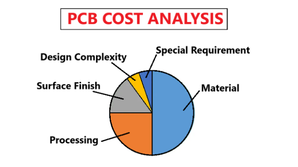
Several factors drive expenses in PCB assembly, starting with board fabrication that feeds into surface-mount technology processes. Layer count and trace density increase material use and handling time, while via types affect drilling costs. Solder mask and silkscreen add minimal fees but accumulate in volume orders. Poor design leads to warpage or delamination, triggering IPC-6012 qualification failures and rework. Engineers must quantify these elements early to target reductions without risking performance.
Component sourcing represents another major expense, often 40 to 60 percent of total assembly bills. Exotic packages demand custom tooling, while fine-pitch leads complicate placement accuracy. Reflow soldering profiles must accommodate mixed technologies, and inadequate stencil apertures cause bridging defects per IPC-A-610 Class 2 allowances. Yield losses from tombstoning or insufficient wetting multiply costs through manual intervention. Process parameters like conveyor speed and oven zoning further influence throughput. Troubleshooting these drivers reveals opportunities for systemic improvements.
Strategies to Reduce PCB Material Costs IPC Class 2
Selecting appropriate substrates heads the list for reducing PCB material costs IPC Class 2. Standard 1.6 mm FR-4 with 170 Tg glass transition temperature meets most thermal demands, eliminating needs for higher-grade alternatives. Thinner copper foils like 1 oz reduce etching waste and support finer features within Class 2 tolerances. Panelization maximizes sheet utilization, aiming for over 80 percent efficiency to minimize perimeter losses. V-scoring or tab routing facilitates depaneling without adding fixtures. These choices lower raw material outlays by 15 to 25 percent in typical runs.
Optimizing stackups prevents symmetric imbalances that cause warpage during reflow. Core and prepreg selections should match CTE values closely, adhering to IPC-6012 guidelines for dimensional stability. Fewer layers consolidate signals, cutting lamination cycles and inspection steps. Blind or buried vias save space but increase costs, so through-hole alternatives suffice for Class 2 signals. Surface finishes like HASL or ENIG balance protection and affordability, with HASL suiting leaded processes. Regular DFM reviews catch these efficiencies before fabrication.
Component Selection for Cost Reduction IPC Class 2
Component selection for cost reduction IPC Class 2 hinges on standard footprints and availability. Prioritizing 0805 or 1206 SMD resistors and capacitors avoids fine-pitch handling premiums associated with 01005 sizes. Leaded parts enable pin-in-paste techniques, combining through-hole reliability with SMT speeds. Reel packaging streamlines pick-and-place operations, reducing feeder changeovers. Dual-sourcing common values mitigates lead time risks without premium pricing. These decisions enhance feeder efficiency and lower kitting expenses.
Avoiding BGA or QFN packages unless essential preserves budget, as they require X-ray inspection beyond basic AOI for Class 2. Standard tolerance parts like 5 percent resistors meet performance needs without 1 percent markups. Mixed-technology boards benefit from grouped placement, minimizing reflow passes. IPC-7351 land patterns ensure optimal solder joints, cutting defects. Volume forecasting secures bulk discounts, stabilizing costs across prototypes to production.
Process Optimizations to Optimize PCB Assembly Costs IPC Class 2
Stencil design plays a crucial role in optimizing PCB assembly costs IPC Class 2 by controlling solder paste volume. Aperture reductions of 10 to 20 percent for fine-pitch components prevent bridging while maintaining voids below Class 2 limits. Laser-cut stainless steel stencils with electropolishing yield consistent deposits. Printer setup with squeegee pressure at 4 to 6 kg/cm ensures uniform transfer. Verification via SPI catches volume variances early.
Reflow profiling tailors peak temperatures to 235 to 245 degrees C for lead-free alloys, avoiding overheating that warps boards. Nitrogen atmospheres optional for Class 2 reduce oxidation but add gas costs, so air profiles suffice with flux selection. Conveyor speeds matching throughput balance cycle times. Post-reflow AOI focuses on Class 2 criteria like heel fillet formation, minimizing manual visual checks.
Selective soldering for through-hole parts streamlines mixed assemblies, using drop-jet fluxers to limit overspray. Wave soldering pallets protect SMT areas, boosting yields. Functional testing at board level catches faults before enclosure, saving field returns.
Troubleshooting Common Cost Overruns in IPC Class 2 Assembly
Engineers frequently encounter bridging from excessive paste, resolvable by stencil trap reliefs and paste rheology checks. Tombstoning arises from mismatched reflow ramps, fixed via symmetric thermal mass distribution. Warpage exceeds 0.75 percent I/100 mm in unbalanced stacks, demanding core adjustments per IPC standards. Component misalignment stems from feeder vibrations, addressed by tension calibration.
Yield dips below 98 percent signal process drifts, prompting CpK analysis on critical joints. Rework spikes from cold joints indicate profile inadequacies, solvable with thermocouple mapping. Documentation gaps cause repeated setups, so standardized travelers prevent this. Proactive SPC monitoring flags trends early, preserving margins.
Conclusion
Implementing these strategies transforms IPC Class 2 assembly from a cost center to a competitive advantage. Material efficiencies, smart component choices, and process tweaks collectively slash expenses by 20 to 30 percent without quality trade-offs. Adhering to IPC-A-610 and related standards ensures compliance amid optimizations. Engineers should iterate DFM feedback loops for continuous gains. Procurement collaboration amplifies savings through volume leverage. These practices deliver reliable boards at scale, meeting market demands effectively.
FAQs
Q1: How can panelization help optimize PCB assembly costs IPC Class 2?
A1: Panelization groups multiple boards on standard sheets, maximizing material use and reducing per-unit fabrication fees. For IPC Class 2, V-grooves or scored lines enable efficient depaneling post-assembly. This approach cuts handling time and scrap, often saving 10 to 20 percent on materials. Ensure rail spacing accommodates pick-and-place fiducials for seamless flow. Troubleshooting misalignments early prevents yield losses.
Q2: What component strategies reduce PCB material costs IPC Class 2?
A2: Focus on standard pitch SMDs like 3216 packages to minimize board real estate and via needs. Group passives near ICs to shorten traces, lowering copper layers. Avoid odd-form parts requiring custom fixtures. IPC-7351-compliant footprints optimize land areas, reducing mask exposures. Balance density with thermal pads for reflow stability.
Q3: Why is stencil optimization key for component selection for cost reduction IPC Class 2?
A3: Proper apertures ensure solder volume matches Class 2 joint criteria, minimizing bridging and voids. Fine-pitch reductions prevent excess paste bridging on dense BGAs. Electropolished edges promote clean release, boosting first-pass yields. Pair with viscosity-matched pastes for consistent printing. This cuts rework, directly lowering labor costs.
Q4: How does DFM impact overall IPC Class 2 assembly efficiency?
A4: DFM aligns designs with Class 2 tolerances, reducing iterations and setup times. Balanced copper distribution averts warpage during reflow. Standard drill sizes streamline tooling. Early reviews catch DFA issues like shadow hiding. Resulting high yields preserve budgets across volumes.
References
IPC-A-610H — Acceptability of Electronic Assemblies. IPC, 2019
IPC-6012DS — Qualification and Performance Specification for Rigid Printed Boards. IPC, 2015
IPC-7351B — Generic Requirements for Surface Mount Design and Land Pattern Standard. IPC, 2010
J-STD-001G — Requirements for Soldered Electrical and Electronic Assemblies. IPC, 2011


