Introduction
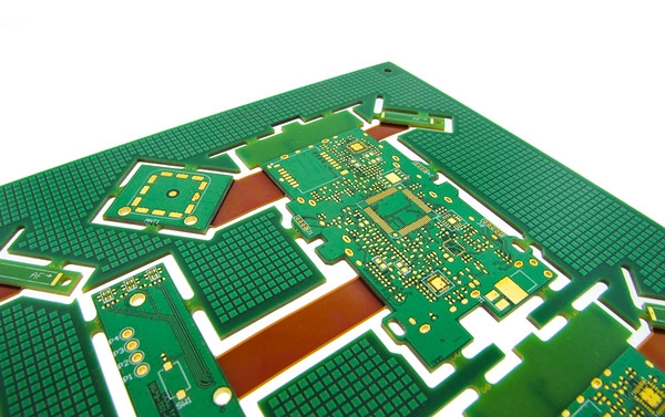
Rigid-flex PCBs combine the benefits of rigid and flexible circuit boards, offering unique solutions for compact and dynamic electronic designs. However, their complex structure poses significant challenges during assembly and fabrication. Design for Manufacturability (DFM) in rigid-flex PCB assembly focuses on optimizing the design to streamline production, reduce costs, and minimize manufacturing defects. For electrical engineers, understanding DFM principles is critical to ensure that designs transition smoothly from concept to production. This article explores the importance of manufacturability in rigid-flex PCBs, key guidelines for PCB fabrication, and best practices for the rigid-flex assembly process. By adhering to industry standards and practical strategies, engineers can achieve reliable outcomes and enhance product performance in demanding applications.
What Is Design for Manufacturability in Rigid-Flex PCBs and Why It Matters
Design for Manufacturability (DFM) refers to the practice of designing products in a way that simplifies their production while maintaining functionality and quality. In the context of rigid-flex PCBs, DFM is essential due to the hybrid nature of these boards, which integrate rigid sections for component mounting with flexible sections for dynamic movement or space constraints. This complexity increases the risk of defects during fabrication and assembly if not addressed early in the design phase.
The significance of rigid-flex PCB DFM lies in its ability to reduce production errors, lower costs, and shorten time to market. Poorly designed boards may lead to issues like misalignment, stress fractures in flex areas, or soldering defects. For engineers, focusing on manufacturability in rigid-flex designs ensures compatibility with assembly equipment, adherence to material limitations, and compliance with industry standards. Ultimately, DFM bridges the gap between innovative design and practical manufacturing, ensuring a seamless production process.
Technical Principles of Manufacturability in Rigid-Flex PCB Assembly
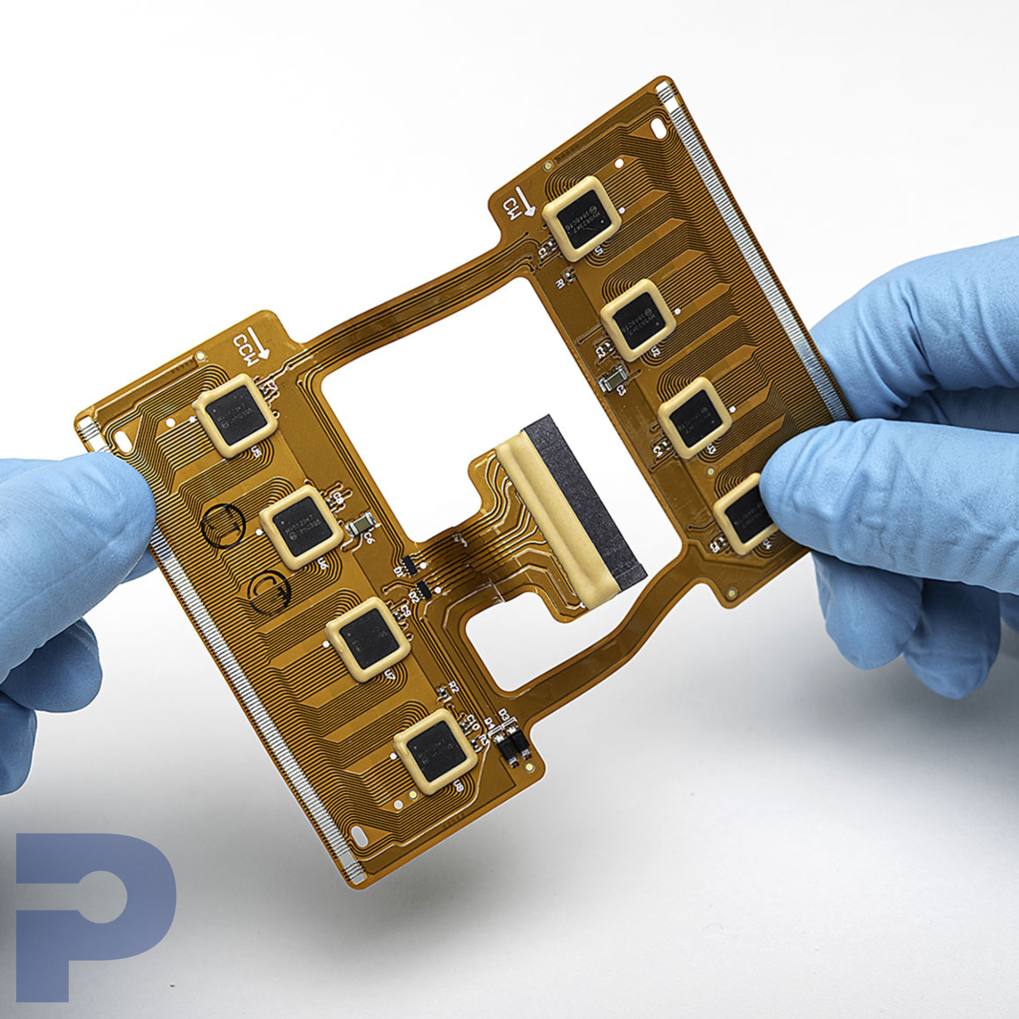
Rigid-flex PCBs present unique challenges due to their mixed construction. Understanding the technical principles behind manufacturability helps engineers anticipate and mitigate potential issues.
Material Selection and Compatibility
The choice of materials directly impacts the manufacturability of rigid-flex PCBs. Rigid sections typically use standard FR-4 or high-Tg laminates, while flexible sections rely on polyimide films for durability under bending. Mismatches in thermal expansion coefficients between these materials can cause delamination or warpage during assembly processes like reflow soldering. Engineers must ensure that selected materials are compatible with each other and suitable for the intended fabrication and assembly conditions.
Stackup Design and Layer Transitions
A well-planned stackup is crucial for rigid-flex PCB DFM. The transition zones between rigid and flexible areas are prone to mechanical stress and signal integrity issues. Abrupt changes in layer count or improper adhesive placement can lead to cracking or peeling. Standards such as IPC-2223C provide guidance on designing sectional stackups to maintain structural integrity and electrical performance. Engineers should minimize layer transitions in high-stress areas and use staggered vias to reduce strain.
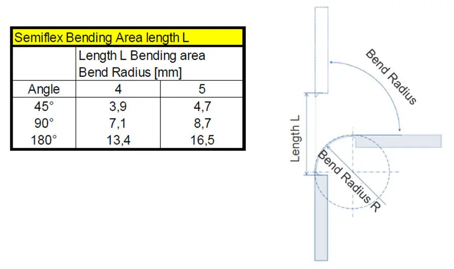
Bend Radius and Flex Area Constraints
The flexible sections of a rigid-flex PCB must withstand repeated bending without failure. A key principle is maintaining an appropriate bend radius relative to the thickness of the flex material. As a general rule, the bend radius should be at least 10 times the thickness of the flex layer to prevent cracking, as outlined in IPC-2223C. Additionally, components and traces should not be placed in bend zones to avoid mechanical damage during use or assembly.
Via and Trace Design for Reliability
Vias and traces in rigid-flex designs require careful consideration to prevent defects. Annular rings around vias must be sufficiently large to accommodate drilling tolerances, especially in rigid sections. In flex areas, traces should run perpendicular to the bend direction to minimize stress, and teardrop pads can enhance reliability at via connections. Adhering to IPC-6013D ensures that these design elements meet manufacturability standards during PCB fabrication.
Practical Solutions and Best Practices for Rigid-Flex PCB Assembly Process
Implementing DFM principles through actionable strategies can significantly improve the rigid-flex assembly process. Below are best practices tailored for electrical engineers to ensure smooth production.
Optimize Panelization for Assembly Efficiency
Panelization, the arrangement of multiple PCBs on a single panel, affects assembly throughput. For rigid-flex designs, engineers should consider breakaway tabs or scoring lines to separate boards without damaging flex sections. Alignment fiducials must be included on both rigid and flex areas to ensure precise component placement during surface mount technology (SMT) processes. This approach minimizes manufacturing defects and enhances compatibility with automated assembly equipment.
Design with Assembly Tolerances in Mind
Rigid-flex PCBs often involve tight tolerances due to their compact nature. Engineers should account for fabrication and assembly variations by providing adequate clearance between components and board edges. IPC-A-600K offers acceptability criteria for printed boards, including tolerances for hole sizes and trace widths. Incorporating these guidelines into the design phase prevents issues like component misalignment or insufficient solder joint formation during the assembly process.
Minimize Stress in Flex-to-Rigid Transitions
Stress concentration at flex-to-rigid transitions is a common cause of failure. To address this, engineers can use gradual transitions with reinforcing materials or adhesives in high-stress zones. Avoiding sharp corners in flex areas and ensuring uniform copper distribution across layers also reduces the risk of cracking. These practices align with IPC-6013D, which specifies performance requirements for rigid-flex boards.
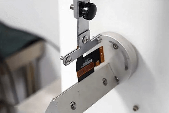
Test and Validate Designs Early
Prototyping and design validation are critical steps in rigid-flex PCB DFM. Engineers should conduct mechanical and thermal stress tests on prototypes to identify potential weak points in flex areas. Electrical testing, including continuity and impedance checks, ensures signal integrity across transitions. Following IPC-9252A guidelines for testability can help establish reliable validation processes, minimizing manufacturing defects before full-scale production begins.
Collaborate with Fabrication Partners
Effective communication with fabrication teams ensures that design intent aligns with manufacturing capabilities. Providing detailed documentation, including stackup diagrams, material specifications, and assembly notes, helps avoid misinterpretation. Engineers should also request design rule checks (DRC) based on fabrication guidelines to identify potential issues early. While specific partners are not mentioned here, adhering to universal standards like ISO 9001:2015 for quality management supports consistent outcomes.
Suggested Reading: High-Performance PCB Assembly: Key Design Considerations 2026
Troubleshooting Common Issues in Rigid-Flex PCB Assembly
During the PCB board assembly process, certain issues frequently arise due to the hybrid nature of these boards. Addressing these challenges proactively can save time and resources.
Warpage and Misalignment
Warpage often occurs due to uneven thermal expansion or improper material selection. To mitigate this, balance copper distribution across layers and use symmetrical stackups. Misalignment during assembly can be reduced by incorporating fiducial markers and ensuring precise panelization. Regular inspection using standards like IPC-A-600K helps detect warpage early in the process.
Solder Joint Failures in Flex Areas
Solder joint failures are common in flex sections due to mechanical stress. Engineers can prevent this by avoiding component placement in bend zones and using flexible solder masks. Additionally, selecting components with compatible thermal profiles reduces stress during reflow, as guided by JEDEC J-STD-020E for moisture and reflow sensitivity classification.
Delamination at Transitions
Delamination at rigid-to-flex transitions often results from poor adhesive bonding or material mismatch. Using high-quality adhesives and ensuring cleanroom conditions during lamination can prevent this issue. Following fabrication guidelines in IPC-6013D ensures that bonding processes meet industry standards for reliability.
Conclusion
Design for Manufacturability in rigid-flex PCB assembly is a critical aspect of achieving a smooth production process. By focusing on material compatibility, stackup design, bend radius constraints, and assembly tolerances, engineers can significantly reduce manufacturing defects. Practical strategies like optimized panelization, stress mitigation, and early validation further enhance the reliability of rigid-flex designs. Adhering to recognized industry standards ensures that designs meet both performance and manufacturability requirements. For electrical engineers, integrating these DFM principles into the rigid-flex assembly process is key to delivering high-quality, cost-effective solutions in today’s competitive electronics landscape.
FAQs
Q1: What are the key considerations for rigid-flex PCB DFM to avoid manufacturing defects?
A1: Ensuring manufacturability in rigid-flex PCB DFM involves prioritizing material compatibility, proper stackup design, and adequate bend radius. Following standards like IPC-2223C for flex design and IPC-6013D for performance helps minimize defects. Additionally, incorporating assembly tolerances and fiducial markers enhances precision during production. Early prototyping and validation are also essential to identify issues before full-scale manufacturing begins.
Q2: How does the rigid-flex assembly process differ from standard PCB assembly?
A2: The rigid-flex assembly process is more complex due to the hybrid structure of the boards. Flex sections require careful handling to avoid stress, and transitions between rigid and flex areas need precise alignment. Special panelization techniques and fiducial markers are often used for accuracy. Standards like IPC-A-600K guide acceptability criteria, ensuring reliable assembly despite these unique challenges.
Q3: What are common causes of defects in manufacturability of rigid-flex PCBs?
A3: Common defects in manufacturability of rigid-flex PCBs include warpage from uneven copper distribution, delamination at transitions due to poor bonding, and solder joint failures in flex areas from mechanical stress. Inadequate bend radius or component placement in flex zones can also cause cracking. Adhering to IPC-6013D and conducting thorough testing helps address these issues effectively.
Q4: How can engineers improve the PCB fabrication guidelines for rigid-flex designs?
A4: Engineers can enhance PCB fabrication guidelines for rigid-flex designs by specifying compatible materials, balancing stackups, and avoiding sharp transitions. Detailed documentation with clear stackup diagrams and assembly notes ensures alignment with fabrication capabilities. Incorporating design rules from IPC-2223C for flex sections and validating designs through prototypes further improves outcomes during the production process.
References
IPC-2223C — Sectional Design Standard for Flexible Printed Boards. IPC, 2016.
IPC-6013D — Qualification and Performance Specification for Flexible and Rigid-Flex Printed Boards. IPC, 2017.
IPC-A-600K — Acceptability of Printed Boards. IPC, 2020.
IPC-9252A — Guidelines and Requirements for Electrical Testing of Unpopulated Printed Boards. IPC, 2008.
JEDEC J-STD-020E — Moisture/Reflow Sensitivity Classification for Nonhermetic Surface Mount Devices. JEDEC, 2014.
ISO 9001:2015 — Quality Management Systems. ISO, 2015.


