Introduction
In modern electronics manufacturing, automated assembly lines have become essential for producing printed circuit boards (PCBs) at scale with consistent quality. Designing for automation requires careful consideration of automated assembly line design considerations from the earliest stages of PCB layout. This approach, often referred to as design for automated assembly (DFAA) or DFA guidelines for PCBs, minimizes errors, reduces cycle times, and lowers costs by aligning the board design with the capabilities of pick-and-place machines, stencil printers, and reflow ovens. Engineers must prioritize features that enable precise machine vision alignment, smooth component handling, and reliable soldering processes. Poor design choices can lead to frequent stops, rework, or yield losses on high-speed lines. By integrating PCB design for automated manufacturing principles, teams can achieve higher throughput and reliability in demanding production environments.
The shift toward surface-mount technology (SMT) dominance amplifies the need for DFAA, as automated lines process thousands of components per hour. Troubleshooting issues like misalignment or solder defects becomes proactive rather than reactive when designs incorporate automation-friendly elements. This article explores key principles, practical solutions, and troubleshooting insights tailored for electric engineers optimizing assembly workflows.
What Is Design for Automated Assembly (DFAA) and Why It Matters
Design for automated assembly (DFAA) encompasses a set of guidelines that optimize PCB layouts specifically for robotic assembly processes. It focuses on simplifying component placement, ensuring machine-readable features, and avoiding geometries that challenge automation equipment. DFA guidelines for PCB extend beyond basic manufacturability to address the unique demands of inline production, such as rapid indexing between stations and minimal operator intervention. In essence, DFAA bridges the gap between design intent and factory floor execution, making PCB design for automated manufacturing a core competency for efficient lines.
The relevance of DFAA intensifies in high-volume scenarios where downtime from design flaws cascades into significant losses. Automated lines rely on fiducials for alignment, consistent orientations for feeder efficiency, and predictable solder behavior to maintain pace. Without these, common issues like tombstoning or bridging halt progress, forcing manual fixes that undermine automation benefits. Adopting DFAA principles also enhances traceability and quality control, aligning with industry expectations for reliable electronics. For electric engineers, mastering these guidelines means fewer prototypes iterations and smoother transitions to production.
Core Principles of Fiducials and Panelization
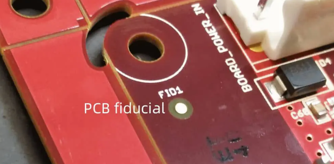
Fiducial marks serve as critical reference points for automated optical alignment in pick-and-place operations. Place global fiducials near opposite corners of the PCB or panel, ensuring they are clear of components, solder mask, and silkscreen obstructions. Local fiducials near fine-pitch devices improve precision for high-density areas. These marks must contrast sharply with the board substrate, typically using exposed copper circles with sufficient diameter and no fill. Proper fiducial design prevents registration errors that misalign entire boards during stencil printing or component placement.
Panelization adapts single PCBs into arrays for efficient automated handling on assembly lines. Use V-scoring or tab routing to allow easy depanelization without stressing components near edges. Maintain uniform rail clearances and breakaway tabs to fit standard line tooling. Avoid irregular panel shapes that complicate fixturing or cause jams in conveyors. This principle directly impacts throughput, as well-paneled arrays enable continuous flow through multiple machines.
Optimizing Component Placement and Orientation
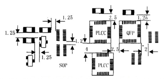
Consistent component orientation streamlines feeder setup and reduces programming time on automated lines. Align polarized parts like diodes and capacitors with visible silkscreen indicators, such as bars or triangles pointing to the cathode or positive terminal. Group similar packages in the same rotational direction to minimize head changes during placement. Reserve the board center for less sensitive components to mitigate warpage effects during reflow. Engineers should simulate placement sequences to identify bottlenecks early.
Strategic placement zones separate high-speed signals from power devices, easing thermal management and inspection. Position tall components away from edges to prevent interference with clamps or vacuum nozzles. Prioritize surface-mount over through-hole where possible, as SMT suits automation better by eliminating selective soldering steps. This organization not only boosts speed but also aids automated optical inspection (AOI) by providing unobstructed views.
Ensuring Adequate Spacing and Clearances
Component spacing prevents solder bridging and facilitates stencil release during paste deposition. Maintain generous gaps between adjacent pads, scaling with package density to accommodate paste volume variations. Part-to-edge clearances protect against damage during depanelization or wave soldering hold-downs. Similarly, distance components from vias and holes to avoid solder wicking or shorting. Solder mask dams between pads further enhance reliability by controlling paste flow.
Board edge and courtyard rules safeguard handling zones for robotic grippers. Define keep-out areas around connectors for mating hardware access. These clearances, when balanced, support dense layouts without compromising automation flow. Troubleshooting spacing issues often reveals root causes like inconsistent paste printing, underscoring the need for design-line synergy.
Land Pattern and Solder Joint Design per IPC-7351
Land patterns form the foundation of reliable automated soldering, dictating paste deposition and reflow outcomes. Follow IPC-7351 guidelines for pad geometry, density levels, and toe/fillet dimensions to match component leads precisely. Non-solder mask defined (NSMD) pads suit fine-pitch while solder mask defined (SMD) pads aid coarser applications. Incorporate thermal reliefs on thicker copper to equalize heating and prevent cold joints.
Via tenting and plug options prevent paste intrusion in high-density boards. Optimize stencil apertures to reduce bridging risks, often by etching smaller openings than pad size. These designs minimize defects like voids or insufficient fillet, common in high-speed reflow profiles. Practical validation through solder paste inspection (SPI) confirms design efficacy before full runs.
Considerations for Soldering and Thermal Processes
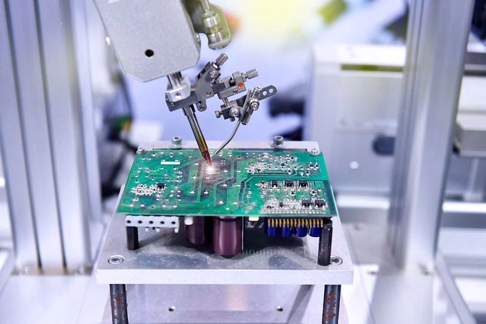
Reflow soldering dominates automated SMT lines, demanding designs tolerant of peak temperatures and ramp rates. Place heat-sensitive components away from large thermal masses to avoid shadowing. Thermal vias under QFNs or BGAs dissipate heat evenly, but cap them to block solder. Wave soldering, if mixed with through-hole, requires orientation to promote fillet formation without bridging.
Per J-STD-001 requirements for soldered assemblies, ensure joints meet class criteria for automated verification. Bake boards pre-assembly to expel moisture, preventing popcorning. These thermal-aware designs sustain line speeds while upholding joint integrity.
Enhancing Inspection and Testability
Accessible test points and probe zones enable in-circuit testing (ICT) without disassembly. Position them on node nets with silkscreen labels for automated probing. Fiducials double as inspection aids for AOI alignment. Embed boundary scan chains for complex BGAs to bypass physical probes.
DFAA incorporates self-test features like daisy-chained nets for continuity checks. These elements reduce escape defects, allowing lines to run at peak efficiency.
Best Practices for Implementing DFAA
Start DFAA early in the design phase with DFM/DFA checklists covering fiducials, spacing, and orientations. Collaborate with assembly partners to align on machine capabilities and tolerances. Use standardized footprints from verified libraries to avoid custom programming. Simulate reflow profiles virtually to predict joint quality.
Panelize with multiples of four for optimal line loading, incorporating break-routes for stress relief. Document DNI parts clearly in assembly drawings. Regular design reviews catch issues before Gerber release. These practices transform potential pitfalls into streamlined production.
Troubleshooting Common DFAA Challenges
Misaligned fiducials often stem from obscured marks or poor contrast, resolved by relocating or resizing them. Tombstoning arises from uneven paste or rapid ramps; adjust stencil thickness and preheat dwells. Bridging signals excessive paste; refine apertures or mask expansion. Warped panels disrupt flatness; symmetrize copper distribution and select low-CTE materials.
Component feeders jamming indicate inconsistent orientations; standardize rotations per IPC-7351. Yield dips post-reflow point to thermal imbalances; add reliefs or vias. Systematic logging pinpoints design tweaks, refining future iterations. Electric engineers benefit from root-cause analysis to evolve DFAA proficiency.
Conclusion
Mastering DFAA principles elevates PCB design for automated manufacturing, ensuring efficient assembly lines with minimal interventions. From fiducials and panelization to spacing and land patterns, each element contributes to seamless automation. Integrating these guidelines per IPC-A-610 acceptability criteria fosters high yields and reliability. Electric engineers who prioritize automated assembly line design considerations gain a competitive edge in fast-paced production. Proactive troubleshooting solidifies these practices, driving sustained improvements.
FAQs
Q1: What are the main automated assembly line design considerations for PCBs?
A1: Key considerations include fiducial placement for alignment, panelization for handling, and consistent component orientations to suit pick-and-place machines. Adequate spacing prevents soldering defects, while optimized land patterns per industry standards ensure reliable joints. These elements minimize line stops and boost throughput in high-volume SMT environments. Focus on simulation and partner feedback for best results.
Q2: How do DFA guidelines for PCB improve automated manufacturing?
A2: DFA guidelines emphasize features like clear polarity marks, generous clearances, and thermal reliefs that align with robotic processes. They reduce errors such as bridging or misalignment, enabling faster cycles and higher yields. By simplifying feeder setups and inspection access, designs support continuous flow. Practical implementation cuts rework, aligning design with factory realities.
Q3: What role do fiducials play in design for automated assembly (DFAA)?
A3: Fiducials provide reference points for machine vision, ensuring precise stencil and component registration. Global ones align panels, while local aid dense areas. Proper design avoids obstructions, preventing offsets that cascade into defects. Troubleshooting poor recognition often involves contrast enhancements. Essential for DFAA in automated lines.
Q4: Why is component spacing critical in PCB design for automated manufacturing?
A4: Spacing averts solder bridges, eases paste release, and protects against mechanical damage during handling. It accommodates nozzle access and AOI views, maintaining line speed. Inadequate gaps lead to frequent pauses for cleaning. Balance density with clearances for optimal DFAA outcomes.
References
IPC-7351B — Generic Requirements for Surface Mount Design and Land Pattern Standard. IPC, 2005
IPC-A-610H — Acceptability of Electronic Assemblies. IPC, 2019
J-STD-001H — Requirements for Soldered Electrical and Electronic Assemblies. IPC/JEDEC, 2018


