Introduction
Building your own printed circuit board assemblies at home brings excitement to electronic projects, but ensuring they last under real-world stress is crucial. DIY PCBA testing lets hobbyists verify reliability without fancy lab equipment, catching issues early to save time and frustration. These simple techniques focus on common failure points like solder joints and component stresses that hobbyists often overlook. By following straightforward home PCBA reliability tests, you can boost confidence in your builds before deploying them in robots, gadgets, or wearables. This guide shares practical steps tailored for electronic hobbyists, drawing from proven engineering principles. Get ready to transform guesswork into reliable results with tools you likely already own.
What Is PCBA Reliability Testing and Why It Matters for Hobbyists
PCBA reliability testing evaluates how well assembled boards endure environmental stresses, mechanical handling, and electrical loads over time. For hobbyists, this means simulating conditions like heat from a battery-powered device or vibrations from a drone motor right on your workbench. Failures such as cracked solder joints or delaminating traces can ruin projects, leading to wasted components and endless debugging. Conducting hobbyist PCBA tests at home prevents these headaches, mimicking professional qualification without the cost. Reliability directly impacts project success, as a board that works on the bench might fail after a few hours of use. Embracing DIY PCBA testing builds skills and ensures your creations stand up to daily abuse.
Key Technical Principles Behind PCBA Reliability
Reliability in PCB assemblies stems from managing thermal expansion mismatches between materials like copper traces and epoxy substrates. When heated, different coefficients of thermal expansion cause stresses at solder joints, potentially leading to fatigue cracks over cycles. Mechanical principles involve board flexure, where warpage from uneven cooling during soldering induces microcracks in vias or pads. Electrical reliability hinges on consistent conductivity, as corrosion or contamination raises resistance and sparks intermittent failures. Humidity accelerates these issues by promoting electromigration in traces under bias voltage. Understanding these mechanisms guides effective home PCBA reliability tests, focusing on stress acceleration without complex simulations.
Vibration testing principles draw from resonance frequencies, where hobbyist assemblies must withstand frequencies up to several kilohertz from motors or speakers. Solder joint integrity follows shear strength models, tested simply by applying controlled bends. Adhesion between layers relies on lamination quality, probed via continuity checks after flexing. These foundational concepts, aligned with IPC standards for assembly performance, empower hobbyists to prioritize high-risk areas. By targeting these principles, DIY electronic testing becomes systematic rather than random poking.
Practical DIY Techniques for Hobbyist PCBA Tests
Start with visual inspection, the cornerstone of any DIY PCBA testing routine. Use a magnifying glass or phone camera macro mode to scan for solder bridges, cold joints showing dull surfaces, or tombstoning where components lift on one end. Check for pad lifting or trace scratches from handling, and inspect undercaps for flux residue that could cause corrosion. This no-cost step catches 80 percent of assembly flaws before powering up. Document findings with photos for before-and-after comparisons in your projects.
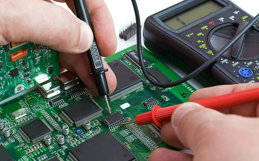
Next, perform electrical continuity tests using a basic multimeter set to ohms or beep mode. Probe every net from schematic to board, verifying low resistance under 10 ohms for traces and infinite for opens. Stress test by gently flexing the board while monitoring continuity to detect hidden cracks. Include power and ground planes, ensuring no shorts between them. This hobbyist PCBA test confirms basic functionality and flags intermittent issues early.
Thermal stress testing simulates operating heat with a heat gun or toaster oven at controlled temperatures around 100 degrees Celsius. Monitor board temperature with an infrared thermometer, cycling heat for 30 minutes on and off five times while watching for delamination bubbles or component shifts. Power the board during cycles to check for thermal runaway in regulators. Cool naturally between cycles to mimic real use. This home PCBA reliability test reveals solder reflow weaknesses without full ovens.
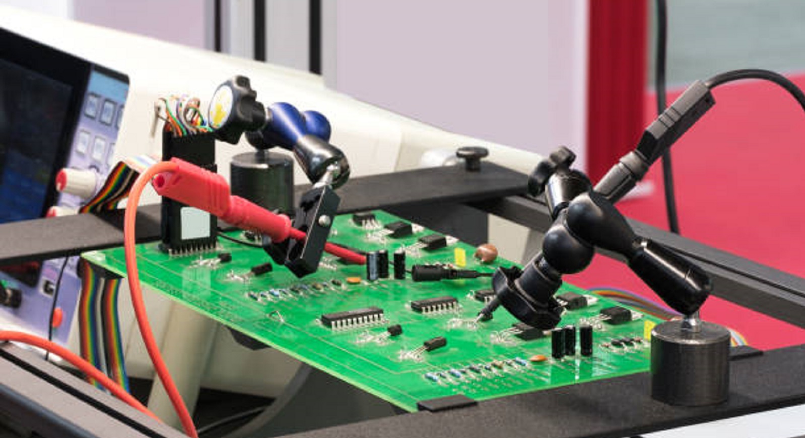
For mechanical reliability, conduct a simple bend test by supporting the board at edges and applying gentle pressure in the center with your finger. Limit deflection to 1–2 mm and cycle 10–20 times, inspecting for cracks via magnification afterward. Test edge connectors by plugging and unplugging 50 times, checking pin wipe and retention. Vibration simulation uses a shaking motor from an old phone or a drill on low speed for 30 minutes. These DIY electronic testing methods mimic handling stresses effectively.
Humidity exposure involves placing the sealed board in a plastic bag with damp salt or sponge for 24–48 hours at room temperature. Follow with a dry bake at 60 degrees Celsius to check for popcorn cracking in components. Power up post-test to detect leakage currents via multimeter voltage drops. This test highlights moisture ingress paths like poor conformal coating or unsealed vias.
Burn-in testing runs the powered assembly continuously for 24–48 hours under nominal voltage, monitoring current draw and temperature rise. Use a fan for cooling if needed, and log any drifts signaling failing capacitors or regulators. Interrupt power periodically to check for stuck relays or memory. This extended hobbyist PCBA test accelerates infant mortality failures.
Troubleshooting Common Issues in DIY PCBA Testing
Spotting cold solder joints during visual checks often traces to insufficient heat or flux, fixed by reflowing with a hot air station at low airflow. If continuity fails post-flex, reinforce weak traces with epoxy or reroute in future designs. Thermal tests revealing warpage suggest uneven copper pour; balance layers symmetrically next time. Vibration failures point to loose screws, so add thread locker or potting compound. Humidity-induced shorts usually stem from unclean flux; adopt no-clean types and bake boards pre-assembly. Log patterns across projects to refine your process, turning tests into iterative improvements.
For persistent power glitches in burn-in, measure ripple voltage with oscilloscope apps on phones if available, indicating bad decoupling caps. Intermittents under stress often mean marginal joints; wick and resolder with fresh paste. Component overheating flags wrong ratings; always derate by 50 percent for hobby use. These troubleshooting steps, guided by J-STD-001 requirements for soldered assemblies, keep your DIY PCBA testing efficient.
Conclusion
DIY PCBA testing empowers electronic hobbyists to build durable assemblies using simple, accessible techniques like visual checks, continuity probes, and thermal cycles. These methods address core reliability principles, from thermal mismatch to mechanical fatigue, without lab costs. Regular home PCBA reliability tests not only prevent field failures but also sharpen your skills for complex projects. Prioritize high-stress areas and document results for continuous refinement. Start small, scale up, and watch your hobby creations thrive under real demands.
FAQs
Q1: What are the basic tools needed for DIY PCBA testing at home?
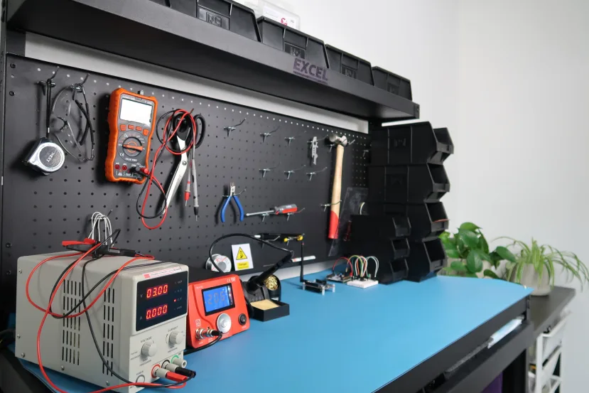
A1: Essential tools include a digital multimeter for continuity and voltage checks, magnifying loupe for inspections, heat gun for thermal stress, and infrared thermometer for monitoring. These enable comprehensive hobbyist PCBA tests covering electrical, visual, and environmental aspects. Start with free apps for logging data to track trends over multiple boards. This setup costs under 50 dollars and handles 90 percent of reliability verification.
Q2: How often should hobbyists perform home PCBA reliability tests?
A2: Test every prototype batch and after major changes like new components. Run full suites before deployment in battery-operated or mobile projects. Quick daily checks suffice for iterations, while burn-in every few weeks catches wear. Consistent DIY electronic testing builds reliability habits without overwhelming your workflow.
Q3: Can DIY PCBA testing detect all potential failures?
A3: Simple techniques spot most assembly flaws like bad joints or contamination but miss ultra-accelerated aging like 1000 thermal cycles. They excel at immediate issues relevant to hobby use. Combine with field logging for long-term insights. Per IPC-A-610 acceptability criteria, visuals and continuity cover essentials effectively.
Q4: What if my board passes DIY tests but fails later?
A4: Post-test failures often involve untested combos like full vibration plus heat. Enhance by stacking stresses sequentially in future runs. Review schematics for underrated parts and add margins. Hobbyist PCBA test evolution through logs prevents repeats.
References
IPC-A-610H — Acceptability of Electronic Assemblies. IPC, 2019
J-STD-001GS — Requirements for Soldered Electrical and Electronic Assemblies. IPC J-STD, 2020
IPC-9701A — Performance Test Methods and Qualification Requirements for Surface Mount Solder Attachments. IPC, 2006


