Introduction
Assembling surface-mount PCBs at home opens up exciting possibilities for electronic hobbyists, but achieving reliable solder joints without professional equipment can be challenging. A toaster oven reflow conversion transforms a common household appliance into a capable reflow soldering station, enabling precise control over the heating process essential for home PCB assembly. By integrating a DIY reflow oven controller, you gain the ability to follow industry-standard temperature profiles that ensure components bond securely without damage. This approach democratizes PCB assembly, making it accessible for prototyping small batches of boards with fine-pitch parts. In the following sections, we explore the principles, build process, and best practices to help you succeed. Whether you're populating a custom sensor board or experimenting with microcontrollers, this setup empowers consistent results.
What Is Reflow Soldering and Why It Matters for Home PCB Assembly
Reflow soldering heats solder paste applied to a PCB, melting it to form electrical and mechanical connections between components and pads. The process involves controlled temperature ramps that activate flux, align parts, and solidify joints without manual intervention, ideal for dense surface-mount designs common in hobby projects. For electronic hobbyists, mastering reflow eliminates the limitations of hand soldering, which struggles with tiny pitches or ball-grid arrays. Converting a toaster oven into a reflow oven provides an affordable entry point, bypassing the high cost of industrial machines while delivering professional-grade outcomes. This method matters because uneven heating leads to defects like voids or bridges, compromising circuit reliability in your builds. Adhering to established thermal profiles ensures your assemblies withstand real-world stresses like vibration or thermal cycling.
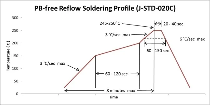
A standard reflow profile consists of four stages: preheat, soak, reflow, and cooling, each serving a specific purpose in solder paste activation and joint formation. During preheat, temperature rises gradually to evaporate solvents and prevent thermal shock to components. The soak phase allows even heat distribution across the board, stabilizing flux activity before peak heating. In the reflow stage, temperature exceeds the solder alloy's liquidus point, forming shiny, concave fillets indicative of good wetting. Cooling must be controlled to avoid stresses that could crack joints or components. These principles, outlined in IPC-7530 guidelines, form the backbone of any effective DIY reflow oven controller.
Proportional-Integral-Derivative (PID) control is the engine driving precise temperature management in a toaster oven reflow conversion. PID algorithms continuously adjust heater power based on feedback from a thermocouple sensor, minimizing overshoot and maintaining setpoint accuracy. Hobbyists implement PID using microcontrollers programmed with tuning parameters derived from oven tests. This closed-loop system compensates for the toaster oven's inherent thermal mass and hot spots, ensuring the PCB experiences a smooth profile. Without PID, manual timing or basic thermostats lead to inconsistent results across runs. Integrating such control elevates home PCB assembly to repeatable precision.
Building a DIY Reflow Oven Controller
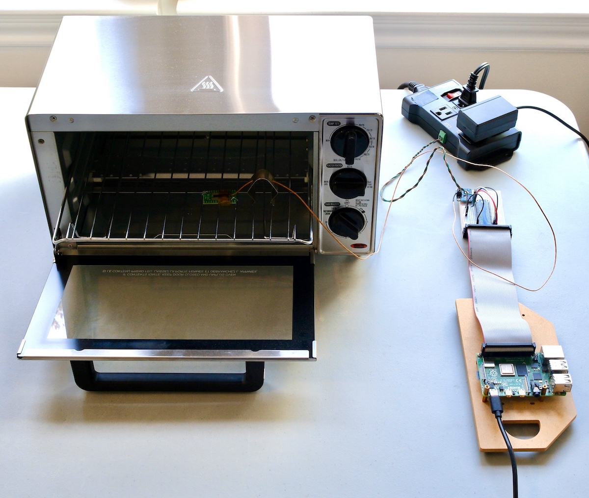
Start with a microcontroller board as the brain of your Arduino reflow oven setup, connecting it to a solid-state relay for safe heater switching and a thermocouple for temperature sensing. Choose a K-type thermocouple amplifier module to convert the sensor's millivolt signal into readable digital values, wiring it directly to the microcontroller's analog input. Add an LCD display and buttons for profile selection and real-time monitoring, programming the firmware to store multiple reflow curves like leaded or lead-free. PID libraries simplify implementation, allowing autotune features to optimize gains for your specific oven. Power the controller externally to isolate it from high-voltage oven circuits, using optocouplers for added safety. This reflow oven kit approach keeps costs low while providing flexibility for experimentation.
Firmware development focuses on state machines that transition through profile stages based on time and temperature thresholds. Upload a sketch that logs data via serial output for post-run analysis, helping refine PID settings. Common profiles mimic industry ramps, such as 1-3 degrees per second preheat rates, adjustable via code. Test empty runs first to verify stability before committing PCBs. Enclose the electronics in a ventilated box mounted outside the oven door. Such a controller turns a basic toaster into a versatile tool for diverse solder pastes.
Step-by-Step Guide to Toaster Oven Reflow Conversion
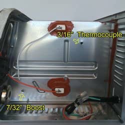
Select a convection toaster oven for uniform heat distribution, avoiding models with exposed heating elements that could radiate directly onto boards. Remove internal racks and clean thoroughly to eliminate food residues, then line the cavity with high-temperature fiberglass insulation if needed for efficiency. Drill a small hole in the side for the thermocouple probe, securing it to mimic PCB position during profiling. Externally mount the DIY reflow oven controller, routing low-voltage wires through the hole while keeping high-voltage separate. Secure the solid-state relay heatsink to dissipate switching heat, and add a fan for cooling if the oven runs hot. Perform dry cycles to baseline performance before assembly.
Safety remains paramount in any toaster oven reflow conversion. Operate in a well-ventilated garage or outdoors to disperse flux vapors, wearing gloves and eye protection against potential spatters. Install a separate circuit breaker and never leave the setup unattended, as overheating risks fire. Use heat-resistant wiring rated above 200 degrees Celsius for all connections. Ground the metal chassis properly to prevent shocks. These precautions ensure reliable home PCB assembly without hazards.
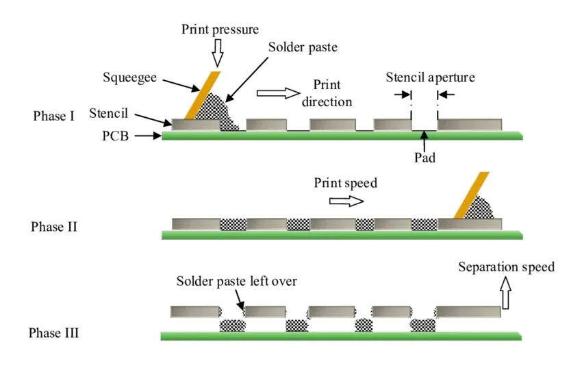
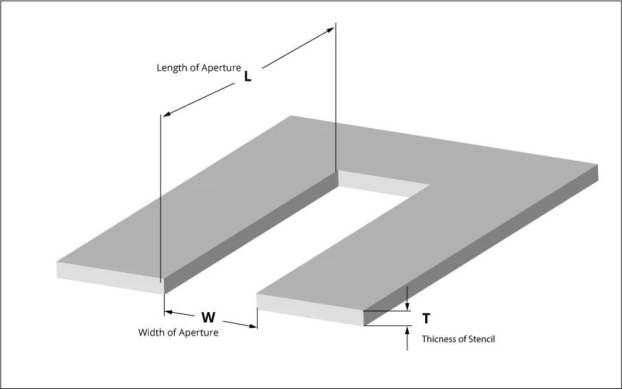
For actual soldering, apply stencil-printed paste evenly, place components, and preheat the empty oven to stabilize. Slide the PCB onto a steel carrier tray for easy insertion, attaching the thermocouple directly to the board center with kapton tape for accurate profiling. Initiate the cycle via the controller, monitoring via LCD or serial plotter. After cooling, inspect joints under magnification for bridges or insufficient fill. Repeat profiling iterations to dial in oven-specific offsets. This methodical process yields professional assemblies.
Best Practices and Troubleshooting for Reliable Results
Profile your setup religiously by taping a thermocouple to a test PCB and running data logger software to capture real-world curves. Adjust PID parameters to match standard shapes, ensuring peak temperatures align with component ratings per J-STD-020 classifications. Preheat boards slowly to avoid warpage, especially on larger panels with asymmetric copper layers. Use no-clean pastes to minimize residue cleanup, and limit batch sizes to maintain uniformity. Store assemblies in anti-static bags post-reflow to protect against handling damage. These practices elevate DIY efforts to production quality.
Common issues like temperature overshoot stem from aggressive PID tuning; reduce proportional gain and increase integral time for smoother response. Hot spots in the oven cause uneven melting, remedied by rotating trays midway or adding baffles for airflow. Tombstoning occurs from rapid cooling gradients, so extend the cooling ramp with fan control. Insufficient reflow leaves dull joints, signaling low peaks, while flux burnout creates splatter if soak is too short. Log every run to correlate defects with profiles, iterating firmware accordingly. Ventilation prevents sensor drift from vapors, maintaining long-term accuracy.
J-STD-020 guidelines emphasize moisture sensitivity, advising bakes for hygroscopic parts before reflow to prevent popcorning. Verify component datasheets for peak limits, as exceeding them risks delamination. In multi-run sessions, allow full cooldowns to reset thermal mass. Document your oven's delta between air and board temperature for consistent offsets. Troubleshooting with these standards ensures robust home PCB assembly.
Conclusion
Converting a toaster oven with a DIY reflow oven controller unlocks professional surface-mount assembly for electronic hobbyists, blending affordability with precision. Key to success lies in understanding reflow profiles, implementing PID control, and profiling religiously against standards like IPC-7530. Practical steps from controller build to safety protocols minimize risks and defects. Troubleshooting empowers ongoing refinement, turning challenges into reliable workflows. Embrace this toaster oven reflow conversion to accelerate your projects, from wearables to IoT devices. With patience and iteration, your home setup rivals commercial lines.
FAQs
Q1: What is a DIY reflow oven controller and how does it work in home PCB assembly?
A1: A DIY reflow oven controller uses a microcontroller, PID algorithm, thermocouple, and relay to automate temperature profiles in a modified oven. It ramps heat through preheat, soak, reflow, and cool stages, ensuring solder paste melts evenly without manual intervention. For hobbyists, this setup handles lead-free or leaded pastes reliably. Wiring focuses on isolation for safety, with firmware storing multiple profiles. Expect initial tuning via test runs for optimal performance.
Q2: Why choose a toaster oven reflow conversion for Arduino reflow oven projects?
A2: Toaster ovens offer convection heating for uniform profiles at low cost, ideal for Arduino reflow oven builds. They provide sufficient thermal mass for small batches, modifiable with insulation for efficiency. PID control compensates quirks like hot spots, delivering repeatable results. This conversion suits prototyping without industrial investment. Safety mods and external controllers keep operations straightforward.
Q3: What are common best practices for a reflow oven kit in toaster oven reflow conversion?
A3: Select convection models, profile with board-mounted thermocouples, and tune PID to avoid overshoot. Use steel trays, limit loads, and ventilate well to manage vapors. Follow J-STD-020 for component handling, baking moisture-sensitive parts first. Inspect post-reflow for fillet quality. Log data for consistency across runs. These steps ensure defect-free home PCB assembly.
Q4: How do you troubleshoot uneven heating in a DIY reflow oven controller setup?
A4: Map hot/cold zones with multiple thermocouples, adding baffles or rotation for balance. Refine PID integral term to stabilize ramps. Verify SSR switching without chatter. Preheat empty for mass equilibrium. Uneven paste or stencil issues mimic thermal faults, so check application first. Iterative profiling resolves most inconsistencies.
References
IPC-7530A — Guidelines for Temperature Profiling for Mass Soldering Processes. IPC.
IPC/JEDEC J-STD-020F — Moisture/Reflow Sensitivity Classification of Nonhermetic Surface Mount Devices. IPC/JEDEC, 2022.