Introduction
Turning a schematic into a working electronic prototype marks an exciting milestone for anyone diving into DIY electronics projects. This process bridges the gap between theoretical design and tangible functionality, allowing hobbyists to test ideas in real-world conditions. For beginners, electronic prototype assembly starts simple but builds essential skills like soldering and troubleshooting. Whether you are assembling circuits for beginners or seeking a breadboard prototyping alternative, a custom PCB offers reliability beyond temporary setups. This guide walks through the journey step by step, focusing on practical methods to achieve success. By the end, you will have the confidence to build your first simple electronic prototype build.
Why Electronic Prototype Assembly Matters for Hobbyists
Electronic prototype assembly transforms abstract diagrams into devices that blink, beep, or compute, validating your circuit design before committing to larger production. In DIY electronics projects, this step uncovers issues like component mismatches or layout flaws that simulations might miss. Hobbyists benefit from hands-on learning, gaining intuition for signal integrity and power distribution. Unlike breadboards, which limit complexity due to loose connections and size constraints, a soldered prototype on a PCB provides a sturdy platform for iterative testing. This approach matters because it accelerates learning and reduces frustration from unreliable temporary builds. Ultimately, mastering assembly empowers creators to tackle more ambitious projects with fewer setbacks.
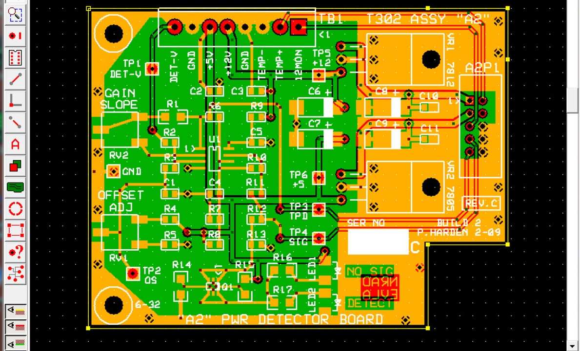
Preparing Your Prototype: From Schematic to PCB Layout Basics
Start by reviewing your schematic to ensure all components match available parts, noting values like resistance or capacitance precisely. Convert the design into a PCB layout using basic principles: place high-current paths away from sensitive signals and maintain adequate spacing to prevent shorts. For a simple electronic prototype build, opt for through-hole technology (THT) components if you are new to soldering, as they forgive minor alignment errors better than surface-mount devices (SMT). Generate Gerber files for fabrication, specifying board thickness around 1.6 mm for standard handling. Double-check the bill of materials (BOM) against datasheets to avoid sourcing errors. This preparation phase sets a solid foundation, minimizing assembly headaches later.
Essential Tools and Materials for Assembly
Gather a soldering iron with adjustable temperature (ideally 300-350°C for leaded solder), fine-tip solder wire (0.7-1.0 mm diameter), and flux for clean joints. Include helping hands or a vise to secure the board, desoldering wick or pump for corrections, and a multimeter for continuity checks. Safety gear like eyewear and ventilation is non-negotiable to handle fumes and splatter. For components, stock resistors, capacitors, LEDs, and IC sockets to ease prototyping. Isopropyl alcohol and a soft brush clean residues post-assembly. These basics enable safe, efficient electronic prototype assembly without overwhelming a beginner.
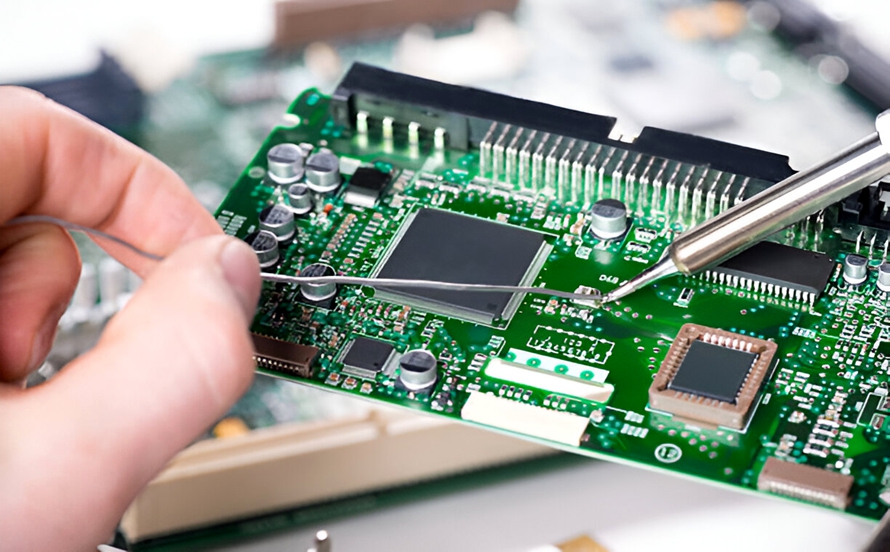
Step-by-Step Guide to Assembling Circuits for Beginners
Begin by tinning the PCB pads lightly with solder for better adhesion, then insert and bend leads of low-profile components like resistors at 45 degrees to secure them. Solder from the underside, heating pad and lead simultaneously for 2-3 seconds to form shiny, concave fillets without bridges. Progress to diodes and capacitors, observing polarity markings to avoid reversal damage. Install ICs last using sockets, ensuring pin 1 orientation matches the silkscreen. After each stage, inspect visually and test continuity to catch issues early. This methodical order streamlines assembling circuits for beginners into a rewarding process.
Transitioning from Breadboard Prototyping Alternative
Breadboards excel for quick tests in DIY electronics projects but falter with vibration, high speeds, or dense layouts due to parasitic capacitance and inductance. A PCB prototype counters these by offering fixed connections and optimized traces, ideal for a breadboard prototyping alternative in reliable builds. Fabricate small panels of 5-10 boards to iterate designs affordably. Solder prototypes mimic production closely, revealing mechanical stresses absent in plug-and-play setups. Hobbyists transitioning here gain permanence, enabling enclosure integration or battery powering. This shift elevates simple electronic prototype builds from fragile experiments to robust demonstrators.
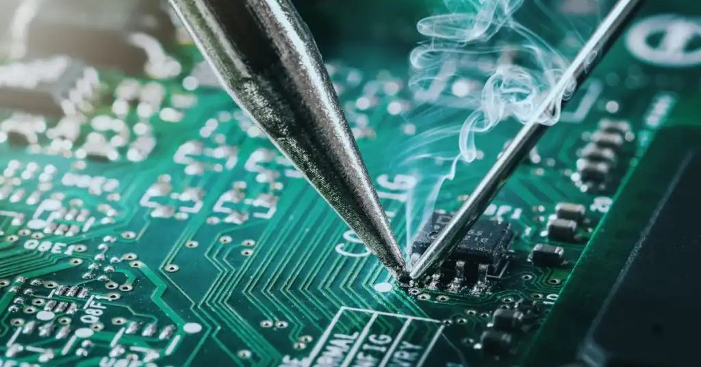
Best Practices and Soldering Standards
Adhere to J-STD-001 requirements for soldered electrical and electronic assemblies to ensure joint integrity, such as avoiding excess solder that could cause tombstoning in THT parts. Maintain iron tip clean and tinned, applying heat uniformly to prevent cold joints, which appear dull and crack under flex. Use no-clean flux sparingly to minimize residue corrosion over time. For quality, follow IPC-A-610 Class 2 criteria for prototypes, accepting minor cosmetic flaws if electrical performance holds. Test power rails with a multimeter before full operation, verifying no shorts below 1 ohm. These practices build durable prototypes aligned with industry benchmarks.
Common Troubleshooting During Electronic Prototype Assembly
Overheated components often lift pads; mitigate by limiting dwell time under 5 seconds and using heat sinks on ICs. Bridge shorts between pins require wick absorption, followed by flux reapplication and retinning. Noisy or erratic behavior signals ground loops; reroute traces or add decoupling capacitors near power pins. If an LED fails to light, swap it first, then check forward voltage drop with the multimeter in diode mode. Component overheating points to current draw mismatches; measure with series ammeter. Systematic checks resolve 90% of issues without redesign.
Advanced Tips for Iterative Prototyping
Once basic assembly succeeds, experiment with mixed THT-SMT for compact designs, using a hot air station for fine-pitch parts. Version control your Gerbers by appending dates, facilitating quick re-spins. Embed test points on pads for oscilloscope probing during debug. Enclose prototypes in 3D-printed cases to assess fit and EMI shielding needs. Document failures with photos to refine future DIY electronics projects. These habits professionalize hobbyist workflows.
Conclusion
Assembling your first electronic prototype demystifies the path from schematic to reality, fostering skills in soldering, testing, and iteration. Key takeaways include methodical component placement, adherence to soldering standards like J-STD-001 and IPC-A-610, and proactive troubleshooting. Moving beyond breadboards to PCBs unlocks reliable DIY electronics projects for beginners. With practice, your simple electronic prototype builds will evolve into sophisticated creations. Embrace the process, and watch ideas come alive.
FAQs
Q1: What are the basic steps in electronic prototype assembly for beginners?
A1: Start with PCB preparation by tinning pads, then solder passive components like resistors first for stability. Progress to active parts, checking polarity and continuity after each group. Clean residues, power up gradually, and test functionality with a multimeter. This sequence ensures assembling circuits for beginners remains straightforward and error-free.
Q2: How does a PCB serve as a breadboard prototyping alternative?
A2: PCBs provide permanent connections free from breadboard's loose wires and capacitance issues, suiting vibration-prone or high-speed DIY electronics projects. Soldering creates compact, reliable layouts for enclosure fitting. Fabricate multiples cheaply for iterations. Ideal for hobbyists advancing to simple electronic prototype build beyond temporary setups.
Q3: What tools are essential for a simple electronic prototype build?
A3: Core items include a temperature-controlled soldering iron, flux-core solder, multimeter, and helping hands. Add desoldering tools and isopropyl alcohol for fixes. These enable safe, precise work without excess gear, perfect for electronic prototype assembly at home.
Q4: How can I troubleshoot common issues in DIY electronics projects?
A4: Inspect for cold joints or bridges visually first, then use multimeter for shorts or opens. Verify power supply matches component ratings and add bypass capacitors if unstable. Reference J-STD-001 for joint quality. Most fixes take minutes with patience.
References
J-STD-001G — Requirements for Soldered Electrical and Electronic Assemblies. IPC, 2017
IPC-A-610H — Acceptability of Electronic Assemblies. IPC, 2019


