Introduction
In PCB manufacturing, maintaining high quality is essential to prevent costly rework, field failures, and production delays. Defects such as missing components, soldering bridges, or misalignment can compromise the reliability of electronic assemblies. AOI equipment, or Automated Optical Inspection systems, plays a critical role by automating the detection of these issues early in the process. This technology enhances AOI equipment quality control, ensuring boards meet stringent requirements before advancing to subsequent stages. By integrating AOI equipment into PCB manufacturing workflows, factories achieve consistent results that align with industry expectations. Ultimately, AOI equipment benefits extend to higher yields and reduced scrap rates.
What Is AOI Equipment and Why It Matters in PCB Manufacturing
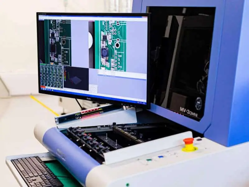
AOI equipment refers to systems that use high-resolution cameras, specialized lighting, and advanced image processing algorithms to inspect printed circuit boards. These machines capture multiple images of the board from various angles and compare them against reference data, such as a golden sample or design files. In PCB manufacturing, AOI equipment operates at key stages like after solder paste printing, component placement, and reflow soldering. This placement allows for timely intervention, minimizing the propagation of errors downstream.
The relevance of AOI equipment stems from the limitations of manual inspection, which is prone to fatigue and inconsistency. Human inspectors might miss subtle defects under high-volume production pressures. AOI equipment defect reduction becomes evident as it detects issues invisible to the naked eye, such as micro-cracks or insufficient solder volume. For electric engineers overseeing production, this translates to reliable process control and adherence to quality benchmarks. Factories relying on AOI equipment PCB manufacturing report improved traceability, as inspection data logs provide detailed defect maps for root cause analysis.
Technical Principles Behind AOI Equipment
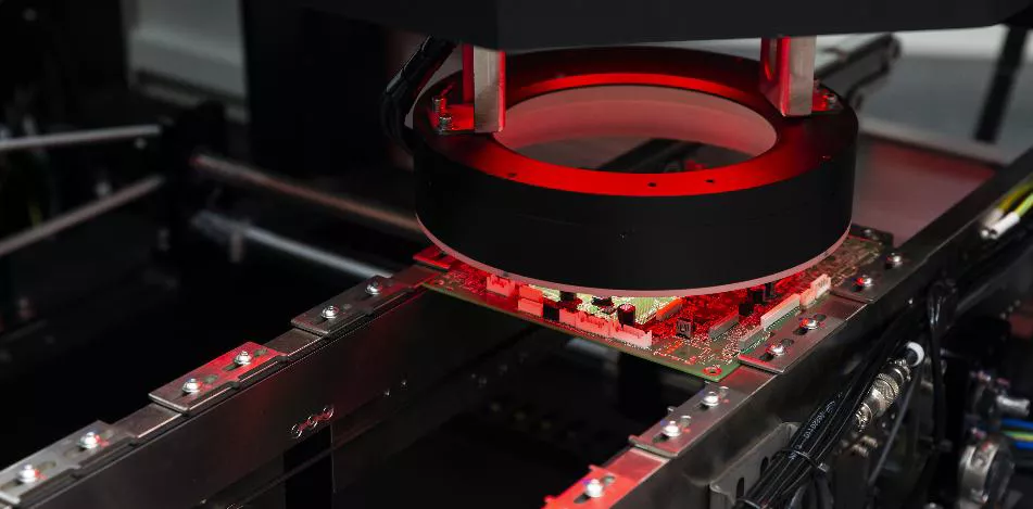
AOI equipment functions through a sequence of image acquisition, analysis, and decision-making. High-speed cameras equipped with LED lighting capture 2D or 3D images of the PCB surface. The lighting setup, often including coaxial, low-angle, and multi-directional sources, highlights features like solder joints and component leads. Software then processes these images using algorithms for edge detection, pattern matching, and color analysis. This enables the system to identify deviations from the programmed reference.
In 2D AOI, the focus lies on top-down views to check component presence, polarity, and basic soldering defects. 3D AOI adds height profiling via structured light or laser triangulation, measuring solder fillet heights and coplanarity. These principles allow AOI equipment error prevention by flagging opens, shorts, bridging, and tombstoning before functional testing. Engineers must consider factors like board warpage or reflective surfaces, which can affect image quality. Calibration routines ensure the system maintains accuracy across production runs.
Defect classification in AOI equipment relies on predefined criteria aligned with visual standards. For instance, the system categorizes solder joint quality based on shape, wetting, and void presence. This automated approach supports high throughput, inspecting hundreds of boards per hour without fatigue. Integration with manufacturing execution systems allows real-time feedback to upstream processes, such as adjusting pick-and-place machines.
How AOI Equipment Detects Common Defects in PCB Manufacturing
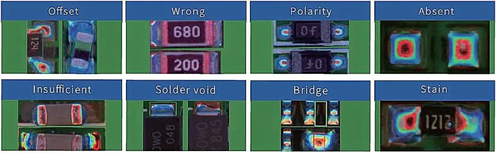
AOI equipment excels at identifying a range of defects that occur during surface-mount technology assembly. Missing or misplaced components trigger immediate alerts, as the system verifies part presence and orientation against CAD data. Soldering defects like insufficient solder, excess solder, or bridging are quantified through image analysis, preventing intermittent failures in the field. Polarity errors on diodes or ICs, along with wrong part values, are also reliably caught.
Bare board inspection via AOI checks for fabrication issues such as trace width variations, drill breakout, or contamination. Post-reflow AOI focuses on joint integrity, detecting lifted leads or head-in-pillow effects common in lead-free processes. These capabilities contribute to AOI equipment defect reduction by localizing problems to specific feeders or stencils. Engineers appreciate the false call minimization features, which use machine learning to refine detection thresholds over time.
In high-density boards with fine-pitch components, AOI equipment's resolution down to microns ensures precision. It complements other tests like in-circuit testing by handling optical-only issues first. This layered approach optimizes overall AOI equipment quality control.
Best Practices for Implementing AOI Equipment in Production
Successful deployment of AOI equipment requires careful programming and integration into the line. Start by importing Gerber and BOM data to create inspection programs, verifying them against known good boards. Regular calibration using test fixtures maintains optical alignment and lighting consistency. Operators should receive training on interpreting false calls and adjusting parameters for new products.
Position AOI stations strategically: pre-reflow for component placement verification and post-reflow for solder joint evaluation. Combine AOI with SPI (solder paste inspection) for comprehensive coverage. Adhering to IPC-A-610J criteria during program setup ensures inspections align with acceptability classes for general electronics or high-reliability applications. Factory-driven insights emphasize offline programming to avoid production downtime.
Data analytics from AOI equipment PCB manufacturing yield process trends, such as recurring feeder issues. Implement feedback loops to upstream equipment for proactive AOI equipment error prevention. Maintenance schedules for cameras and software updates sustain performance. These practices maximize AOI equipment benefits like yield improvement and cost savings.
Following IPC-9716 guidelines for AOI systems setup establishes robust process control parameters. This includes defining inspection zones and tolerance bands. Quality teams benefit from standardized reporting formats that support ISO 9001:2015 quality management principles.
Insights from Factory Integration of AOI Equipment
In a typical high-mix PCB assembly line, AOI equipment handles panel sizes from prototypes to full production runs. Engineers observe that dual-lane AOI configurations balance speed and accuracy for volume manufacturing. Troubleshooting common challenges, like glossy component tops causing reflections, involves optimizing lighting angles. Over time, yield data reveals patterns, such as stencil wear contributing to paste defects.
Combining AOI with X-ray for hidden joints provides holistic coverage without slowing throughput. Electric engineers value the non-contact nature, preserving delicate assemblies. Long-term, AOI equipment fosters continuous improvement by benchmarking against historical defect Pareto charts.
Conclusion
AOI equipment transforms PCB manufacturing by delivering precise, repeatable inspections that drive defect reduction and quality enhancement. From technical image processing to practical line integration, it addresses key pain points in assembly processes. Factory teams leveraging AOI equipment quality control achieve compliance with standards while boosting efficiency. The AOI equipment benefits, including error prevention and yield gains, make it indispensable for modern electronics production. Electric engineers can rely on this technology to ensure robust, reliable boards ready for end-use.
FAQs
Q1: What role does AOI equipment play in defect reduction during PCB manufacturing?
A1: AOI equipment defect reduction occurs through automated scanning that detects issues like missing parts or solder bridges early. Placed after key processes, it halts faulty boards, minimizing rework. This factory-aligned approach aligns with visual standards, improving overall yields without human variability. Engineers use logged data for process tweaks.
Q2: How does AOI equipment enhance quality control in PCB assembly?
A2: AOI equipment quality control involves high-res cameras comparing boards to references for consistency. It flags subtle defects such as polarity errors or joint voids, ensuring compliance. Integration at multiple stages provides layered verification, reducing escapes to functional tests. This supports reliable production outputs.
Q3: What are the main benefits of AOI equipment in PCB manufacturing?
A3: AOI equipment benefits include faster inspections, lower false rejects via algorithms, and data-driven insights. It prevents error propagation, cuts scrap, and scales for high volumes. Factories gain traceability for audits, enhancing process stability. Electric engineers appreciate the precision for complex boards.
Q4: Can AOI equipment prevent common errors in SMT processes?
A4: Yes, AOI equipment error prevention targets placement offsets, paste misalignment, and reflow defects. By verifying at pre- and post-reflow, it corrects feeder or printer issues promptly. Programmed tolerances match assembly classes, avoiding field failures. This proactive stance optimizes line efficiency.
References
IPC-A-610J — Acceptability of Electronic Assemblies. IPC, 2024.
IPC-9716 — Requirements for Automated Optical Inspection (AOI) Systems. IPC, 2024.
ISO 9001:2015 — Quality Management Systems. ISO, 2015.


