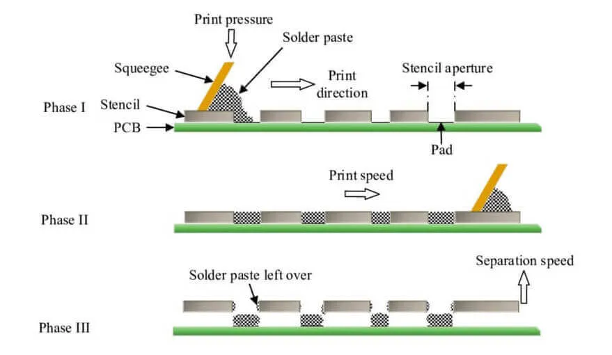
Introduction
In surface mount technology assembly, achieving precise solder paste deposition is essential for reliable solder joints and overall PCB performance. Mounted stencils, which are framed for stability, play a critical role in controlling solder paste volume during the printing process. Variations in stencil design and mounting can lead to inconsistent solder deposition, resulting in defects like insufficient paste bridging or excess paste causing shorts. Electrical engineers often troubleshoot these issues by analyzing factors such as stencil thickness, aperture size, area ratio, and aspect ratio. This article provides a practical analysis of how mounted stencils influence solder paste volume, offering actionable insights for optimizing SMT processes. Understanding these dynamics helps minimize rework and improve yield in high-volume production.
Understanding Mounted Stencils in SMT Assembly
Mounted stencils consist of a thin metal foil, typically laser-cut with precise apertures, stretched and secured within a rigid frame. This framing provides consistent tension across the stencil surface, which is vital for repeatable solder paste transfer. Unlike frameless stencils that require external tensioning systems, mounted versions maintain flatness over extended print runs, reducing variability in solder paste volume. The frame absorbs stresses from repeated squeegee passes, preventing distortion that could alter aperture dimensions or gasketing against the PCB. In practice, engineers select mounted stencils for medium to high-volume assembly where uniformity in solder deposition directly impacts joint quality. Proper mounting ensures the stencil aligns accurately with pads, facilitating controlled solder paste release.
Key Technical Factors Affecting Solder Paste Volume
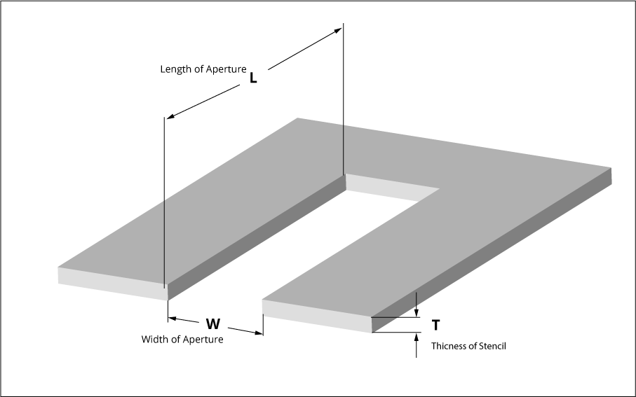
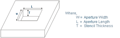
Stencil thickness directly determines the initial solder paste volume transferred to the pads, as thicker foils hold more paste per aperture. Common thicknesses range from finer pitches requiring thinner foils for clean release to larger components needing more volume. However, thicker stencils demand higher squeegee pressure to fill apertures fully, and poor release can leave residue, reducing effective solder paste volume. Aperture size influences the surface tension dynamics during paste release; smaller apertures challenge release efficiency due to increased wall contact area. Engineers must balance these to avoid underfill or overfill conditions that compromise reflow soldering. Area ratio and aspect ratio serve as primary metrics for predicting deposition performance.
Area Ratio and Aspect Ratio: Core Metrics for Release Efficiency
Area ratio, defined as the aperture opening area divided by the aperture wall area, is a key predictor of solder paste release. According to IPC-7525 guidelines, an area ratio greater than 0.66 ensures reliable paste transfer by minimizing wall adhesion relative to the open area. Lower ratios lead to incomplete deposition, where paste clings to walls, reducing solder paste volume on pads. Aspect ratio, the aperture width divided by stencil thickness, complements this; values above 1.5 promote clean snap-off during printing. For fine-pitch components, engineers calculate both ratios early in design to avoid print defects. These metrics guide stencil optimization, directly linking geometry to solder deposition consistency.
How Stencil Mounting Influences Deposition Dynamics
Mounting a stencil in a frame applies uniform tension, typically 15 to 25 Newtons per linear centimeter, which enhances gasketing and squeegee snap-off. This tension prevents foil deflection under pressure, ensuring apertures fill completely and release paste evenly across the board. Without proper mounting, stencil warpage can cause uneven solder paste volume, with high spots leading to excess deposition and lows resulting in skips. Framed stencils excel in maintaining planarity over thousands of prints, unlike tensioned frameless types that may loosen over time. Engineers observe that well-mounted stencils reduce volume variation by up to 10 percent in SPI measurements. Troubleshooting starts with verifying frame integrity and tension levels before adjusting print parameters.
Practical Measurement and Analysis of Solder Paste Volume
To quantify solder paste volume, engineers use solder paste inspection systems that employ 3D laser scanning to measure deposit height, area, and volume post-print. Consistent mounted stencil performance shows volume uniformity within 10 percent across apertures, aligning with process windows for reflow. Variations often trace back to aperture size mismatches or suboptimal area ratios, where smaller features underperform. In analysis, compare printed volumes against design targets derived from component land patterns. Adjust stencil thickness iteratively for mixed-technology boards, thinner for QFNs and thicker for connectors. Data logging from multiple runs reveals mounting effects, such as tension decay correlating with volume drift.
Best Practices for Optimizing Mounted Stencil Performance
Select stencil thickness based on smallest aperture size, aiming for aspect ratios exceeding 1.5 per IPC-7525 recommendations. Laser-cut apertures with trapezoidal walls to improve paste release, reducing bridging risks. Mount stencils with calibrated tension meters to ensure even pull, and clean frames regularly to prevent paste buildup affecting flatness. Use nano-coatings on foil surfaces to lower surface energy, enhancing solder paste volume consistency without altering geometry. Print at 25 to 45 millimeter per second squeegee speed, optimizing for paste rheology. Validate setups with gauge repeats, targeting 75 to 125 percent volume transfer efficiency.
Troubleshooting Common Deposition Issues with Mounted Stencils
Insufficient solder paste volume often stems from low area ratios or excessive stencil thickness, starving fine-pitch pads. Inspect for bridging by checking aspect ratios; elongate apertures if needed to boost ratios. Excessive volume from thick stencils causes tombstoning; step-down areas for mixed pitches. Mounting looseness manifests as random skips; retension or inspect frame mesh for wear. Warped PCBs exacerbate issues, requiring fixture support during printing. Systematic root cause analysis, starting with SPI data, resolves most stencil-related solder deposition problems efficiently.
Conclusion
Mounted stencils significantly impact solder paste deposition volume through tension, flatness, and geometric precision. Optimizing stencil thickness, aperture size, area ratio, and aspect ratio ensures uniform transfer critical for robust assemblies. Practical analysis via SPI and adherence to standards like IPC-7525 minimize defects and boost yields. Engineers benefit from proactive design and maintenance routines tailored to production volumes. Implementing these strategies leads to reliable SMT processes and fewer troubleshooting cycles. Focus on these elements for enhanced solder paste volume control in your next project.
FAQs
Q1: What is the ideal area ratio for consistent solder paste volume in stencil design?
A1: The area ratio, calculated as aperture opening area over wall area, should exceed 0.66 for reliable solder paste release. This guideline from IPC-7525 prevents paste adhesion issues, ensuring adequate solder deposition on pads. Lower ratios suit coarser features but risk underfill in fine-pitch applications. Always verify with print trials for your paste type.
Q2: How does stencil thickness affect solder paste volume during deposition?
A2: Thicker stencils deposit higher solder paste volume, suitable for larger components needing robust joints. However, they challenge release in small apertures due to poorer aspect ratios. Balance thickness with pitch density, typically 100 to 125 microns for general use. Monitor via SPI to stay within process tolerances.
Q3: Why do mounted stencils outperform frameless ones in solder paste volume control?
A3: Mounted stencils provide stable tension and flatness, reducing volume variation over high-volume runs. Frameless types depend on printer tensioning, prone to drift and uneven gasketing. This consistency minimizes skips and bridges in solder deposition. Choose mounted for production exceeding 100 boards per setup.
Q4: What role does aspect ratio play in troubleshooting solder paste deposition issues?
A4: Aspect ratio, aperture width over stencil thickness, above 1.5 promotes clean paste snap-off. Low ratios cause incomplete transfer, leading to low-volume defects. Adjust by thinning stencil or widening apertures. Combine with area ratio checks for comprehensive stencil optimization.
References
IPC-7525B — Stencil Design Guidelines. IPC, 2011
J-STD-005B — Requirements for Soldering Pastes. IPC, 2011


