Introduction
Through-hole technology (THT) remains a vital method in PCB assembly, especially for applications requiring robust mechanical connections. Stronger THT solder joints are critical for ensuring reliability in high-stress environments like automotive, industrial, and aerospace systems. Weak solder joints can lead to failures, causing costly downtime or safety issues. This article explores proven techniques to improve solder joint strength in THT assembly. Aimed at electrical engineers, it provides practical insights into enhancing PCB soldering quality. From understanding joint mechanics to applying best practices, the focus is on actionable steps aligned with industry standards. By mastering these methods, engineers can achieve durable connections and reduce failure risks in their designs.
What Is THT Soldering and Why It Matters
Through-hole technology involves inserting component leads into drilled holes on a PCB and soldering them to pads on the opposite side. Unlike surface-mount technology, THT offers superior mechanical strength due to the physical anchoring of components. This makes it ideal for connectors, power components, and devices subject to vibration or thermal stress. Stronger THT solder joints directly impact the longevity and performance of electronic assemblies. A poor joint can result in cracks, open circuits, or intermittent failures, especially under mechanical or thermal cycling. For engineers, ensuring robust PCB soldering is not just about meeting specifications but also about guaranteeing product reliability in demanding conditions. The significance of this process cannot be overstated in critical applications where failure is not an option.
Related Reading: Essential Guide: Identifying Through-Hole Components for Electronics Beginners
Technical Principles Behind THT Solder Joint Strength
Solder joint strength in THT assemblies depends on several engineering factors. First, the wetting of solder to the component lead and PCB pad is fundamental. Good wetting ensures a strong metallurgical bond, reducing the risk of voids or weak spots. The solder alloy, typically a tin-lead or lead-free mix, must flow evenly into the hole and form a fillet around the lead. Second, the thermal profile during soldering affects joint integrity. Excessive heat can degrade the PCB material or cause component damage, while insufficient heat may lead to cold joints with poor adhesion. Third, the design of the hole and pad plays a role. Proper hole size ensures adequate solder fill, while the pad area supports fillet formation. Lastly, mechanical stress from vibration or thermal expansion can weaken joints over time if not addressed during design and assembly.

Factors Affecting Solder Joint Reliability
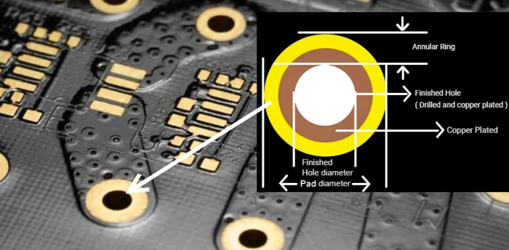
Several elements influence the reliability of THT solder joints. Component lead cleanliness is crucial, as contaminants like oxides prevent proper solder bonding. The PCB surface finish, such as HASL or ENIG, must be compatible with the solder type to ensure adhesion. Hole diameter and annular ring size are also critical. If the hole is too tight, solder may not flow properly, while a hole too large can reduce mechanical support. Thermal cycling, where temperature changes cause expansion and contraction, often leads to fatigue cracks in joints. Additionally, the choice of flux impacts soldering quality. Flux removes oxides and promotes wetting, but insufficient or incorrect flux can result in defective joints. Engineers must consider these factors to improve solder joint strength in their assemblies.
Related Reading: Exploring Different Finishes for FR 4 PCBs: HASL, ENIG, and More
Practical Solutions to Achieve Stronger THT Solder Joints
Achieving stronger THT solder joints requires a combination of design optimization, process control, and material selection. Below are actionable techniques for engineers to enhance PCB soldering outcomes.
Optimize PCB Design for Soldering
Design plays a pivotal role in joint strength. Ensure hole diameters match component leads as per industry guidelines like IPC-2221B, which provides standards for generic PCB design. A slightly larger hole allows solder to flow through, forming a complete barrel. Annular rings should be wide enough to support a robust fillet, typically following minimum dimensions outlined in IPC-6012E for rigid boards. Thermal relief patterns can prevent heat dissipation issues during soldering, ensuring even temperature distribution. Proper spacing between holes avoids solder bridging and facilitates inspection. Engineers should also consider pad shapes that maximize contact area without compromising board integrity.
Select Appropriate Materials
Material choice directly affects soldering quality. Use solder alloys suited for the application, such as SAC305 for lead-free assemblies, which offers good mechanical properties. Flux selection must align with the solder type and PCB finish to ensure effective oxide removal. Boards with compatible surface finishes enhance wettability, reducing defects. Component leads should be free of oxidation or coatings that hinder bonding. Following material guidelines in IPC J-STD-001H helps maintain consistency in achieving reliable joints.
Related Reading: Selecting the Right Solder for THT Assembly: A Comprehensive Guide
Control Soldering Process Parameters
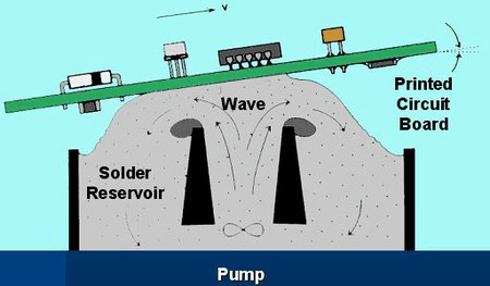
Process control is essential for consistent results. Maintain soldering temperature within the range recommended by IPC J-STD-001H to avoid thermal damage or cold joints. For hand soldering, use a tip temperature that matches the solder alloy’s melting point, ensuring quick and effective bonding. In wave soldering, adjust conveyor speed and preheat stages to achieve uniform heat across the board. Monitor solder bath contamination to prevent impurities from weakening joints. Flux application should be precise, covering only the necessary areas to avoid residue buildup that could cause corrosion over time.
Enhance Mechanical Support
Mechanical stress often causes joint failure in THT assemblies. Adding strain relief, such as securing large components with adhesive before soldering, reduces stress on joints. For connectors or heavy parts, consider using mounting hardware to distribute load away from solder points. Clinching leads after insertion provides additional anchoring, preventing movement during soldering. These steps, aligned with assembly practices in IPC J-STD-001H, ensure joints withstand vibration and handling.
Inspect and Test Joint Quality
Post-soldering inspection is critical to verify joint strength. Visual checks should confirm fillet formation and absence of cracks or voids, adhering to acceptance criteria in IPC-A-600K. Automated optical inspection can detect surface defects, while X-ray imaging reveals internal voids in the solder barrel. Mechanical testing, such as pull strength tests, evaluates joint durability under stress. Thermal cycling tests assess performance under temperature variations, identifying potential fatigue issues. Regular inspection following IPC standards ensures defects are caught early, allowing for rework before deployment.
Troubleshooting Common THT Solder Joint Issues
Even with best practices, challenges arise during THT soldering. Cold joints, characterized by a dull appearance and poor adhesion, often result from insufficient heat or flux. Rework by reheating with adequate flux to restore bonding. Solder voids within the hole can weaken joints, typically caused by outgassing or poor wetting. Adjusting preheat settings or using a vacuum desoldering tool for rework can address this. Cracked joints, often due to thermal stress, require design adjustments like adding thermal relief or reducing temperature gradients during soldering. Insufficient fillet formation may indicate improper hole size or solder volume, necessitating a review of design parameters against IPC-2221B guidelines. Documenting and analyzing failures helps refine processes for future assemblies.
Related Reading: Soldering Troubleshooting: Diagnosing and Fixing Common Solder Joint Issues
Conclusion
Improving THT solder joint strength is a multifaceted task that demands attention to design, materials, and process control. By optimizing PCB layouts, selecting compatible materials, and adhering to strict soldering parameters, engineers can significantly enhance joint reliability. Regular inspection and troubleshooting further ensure that defects are minimized. Aligning practices with established standards like IPC J-STD-001H and IPC-6012E provides a solid foundation for achieving stronger THT solder joints. For electrical engineers, mastering these techniques translates to more durable PCB soldering outcomes, ultimately supporting the performance and safety of electronic systems in critical applications.
FAQs
Q1: How can I improve solder joint strength in THT assemblies?
A1: To improve solder joint strength in THT assemblies, focus on proper hole and pad design as per IPC-2221B guidelines. Use compatible solder alloys and flux, control soldering temperatures, and ensure component leads are clean. Adding mechanical support like clinching or adhesives reduces stress. Regular inspection using IPC-A-600K criteria helps catch defects early for stronger, reliable joints.
Q2: What causes weak THT solder joints on a PCB?
A2: Weak THT solder joints on a PCB often result from poor wetting due to contaminated leads or pads. Incorrect hole sizes, insufficient heat during soldering, or improper flux application can also contribute. Thermal stress or mechanical vibration may cause cracks over time. Following PCB soldering standards like IPC J-STD-001H minimizes these risks through controlled processes.
Q3: Why is PCB soldering critical for THT component reliability?
A3: PCB soldering is vital for THT component reliability because it forms the electrical and mechanical bond between components and the board. Stronger THT solder joints withstand vibration, thermal cycling, and stress in demanding environments. Poor soldering leads to failures like open circuits or cracks. Adhering to standards ensures consistent quality and long-term performance in electronic systems.
Q4: How do I inspect THT solder joints for defects?
A4: Inspect THT solder joints by checking for proper fillet formation and surface finish per IPC-A-600K standards. Use magnifying tools for visual defects like cracks or cold joints. X-ray inspection reveals internal voids in the solder barrel. Mechanical and thermal tests assess durability. Consistent checks during PCB soldering ensure early detection and correction of issues.
References
IPC-2221B — Generic Standard on Printed Board Design. IPC, 2012.
IPC-6012E — Qualification and Performance Specification for Rigid Printed Boards. IPC, 2020.
IPC J-STD-001H — Requirements for Soldered Electrical and Electronic Assemblies. IPC, 2021.
IPC-A-600K — Acceptability of Printed Boards. IPC, 2020.


