Introduction
In advanced PCB designs, achieving reliable solder paste deposition is crucial for high-density surface mount technology assemblies. Laser-cut SMT stencils play a pivotal role by delivering precise apertures that ensure consistent solder volume on pads. These stencils outperform traditional methods in handling fine-pitch components, reducing defects like bridging or insufficient paste. Engineers often face challenges with paste release in tight spaces, where laser cutting accuracy proves essential. This article explores the SMT stencil manufacturing process, focusing on key factors like stencil aperture quality and stencil edge finish. By understanding these elements, you can optimize your PCB assembly yields.
What Are Laser-Cut SMT Stencils and Why They Matter
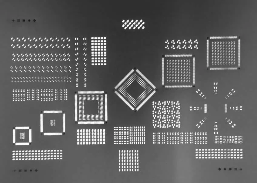
Laser-cut SMT stencils consist of thin metal foils, typically stainless steel, with precisely machined apertures matching PCB pad layouts. Unlike chemical-etched stencils, which can produce undercuts and rough walls, laser cutting vaporizes material to form clean, tapered apertures. This results in superior stencil aperture quality, especially for pitches below 0.5 mm. In high-volume production, these stencils minimize solder paste defects, supporting advanced designs with micro-BGAs and QFNs. Their importance grows with shrinking component sizes, where even minor inaccuracies lead to rework. For electric engineers troubleshooting assembly lines, selecting laser-cut SMT stencils aligns with demands for repeatability and precision.
The relevance extends to mixed-technology boards, where through-hole and SMT coexist. Laser-cut versions handle complex geometries without the alignment issues common in etched stencils. They also facilitate step stencils for varying thicknesses, optimizing paste volume across component types. Industry guidelines, such as IPC-7525, emphasize stencil design for optimal paste transfer efficiency. Ultimately, these stencils reduce first-pass yield losses, saving time and costs in prototyping and production.
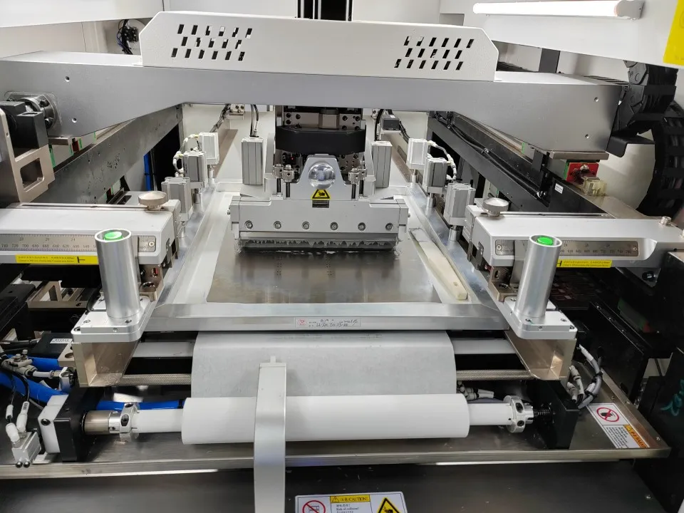
The SMT Stencil Manufacturing Process
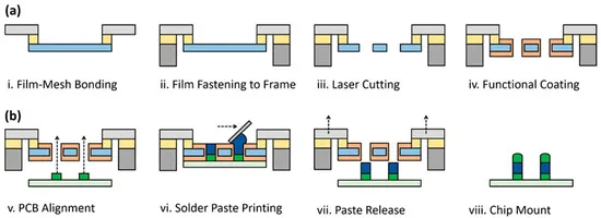
The SMT stencil manufacturing process begins with material selection and preparation. Engineers provide Gerber or CAD files defining aperture shapes and positions. The foil, often mounted on a frame for stability, undergoes laser ablation using high-power lasers like fiber or YAG types. The laser beam focuses to a micron-scale spot, sequentially cutting apertures from the top down, creating a natural trapezoidal profile. Post-cutting, the stencil receives cleaning to remove debris, followed by electropolishing if needed for enhanced surface finish.
Framing integrates the foil into a rigid structure, typically aluminum or stainless steel, using tensioning methods to prevent warping during printing. Inspection verifies aperture dimensions and alignment using optical comparators or automated systems. This step ensures compliance with design tolerances before coating options like nano or anti-stick layers are applied. Troubleshooting common issues, such as residue buildup, involves refining laser parameters like power and speed. The entire process, from file to finished stencil, supports rapid turnaround for prototypes.
Quality checks focus on positional accuracy and wall straightness. Deviations here can cause uneven paste deposition, leading to tombstoning or voids. Advanced systems employ fiducials for precise registration. For multi-level stencils, laser welding combines foils of different thicknesses seamlessly.
Laser Cutting Accuracy and Stencil Aperture Quality
Laser cutting accuracy defines the precision of aperture placement and size, critical for fine-pitch applications. Modern systems achieve tight tolerances through stable beam delivery and motion control, minimizing thermal distortion. This accuracy supports area ratios above 0.66, as recommended in IPC-7525 for reliable paste release. Compared to etching, laser methods avoid chemical undercuts, yielding straighter walls and sharper corners. Engineers benefit from this in designs with 01005 components, where misalignment amplifies defects.
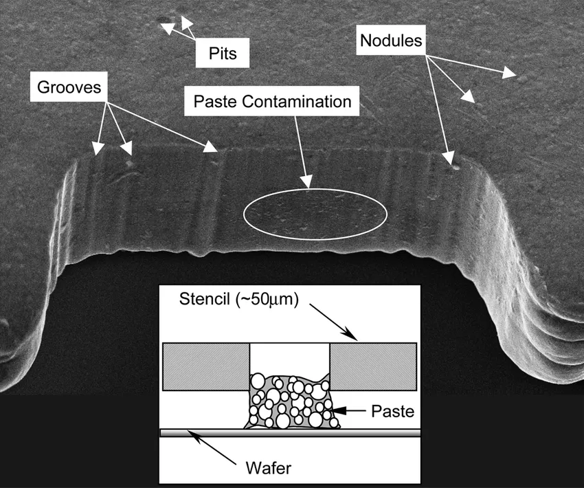
Stencil aperture quality hinges on wall smoothness and taper angle. The laser's Gaussian beam profile naturally tapers walls, aiding paste withdrawal and reducing stringing. Striations from the cut can trap paste if unaddressed, but post-processing like electropolishing mitigates this effectively. Troubleshooting poor quality often reveals suboptimal laser settings or foil inconsistencies. Consistent quality ensures uniform solder joints, vital for signal integrity in high-speed boards. Optical microscopy during inspection reveals these traits early.
Factors influencing accuracy include foil thickness, typically 75 to 150 microns, and environmental controls like vibration isolation. Multi-pass cutting refines edges for ultra-fine features. In practice, validating against pad layouts prevents offset errors during printing.
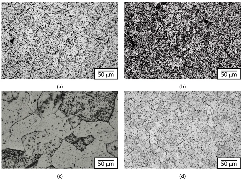
Fine-Grain Stainless Steel and Stencil Edge Finish
Fine-grain stainless steel elevates stencil performance through its refined microstructure. This material offers superior fatigue resistance and smoother surfaces compared to standard grades, enhancing longevity under repeated squeegee cycles. Its smaller grain size minimizes burrs during laser cutting, contributing to excellent stencil edge finish. For low area ratio apertures, fine-grain foils improve paste transfer efficiency, reducing skips on small pads. Engineers specifying this material troubleshoot wear-related issues proactively.
Stencil edge finish directly impacts printing reliability. Laser cutting leaves a characteristic finish with minimal heat-affected zones, but electropolishing removes micro-roughness for mirror-like walls. This process dissolves surface peaks, optimizing release properties without altering dimensions. Poor edge finish manifests as bridging in high-density arrays, often traced to inadequate polishing. Combining fine-grain steel with polishing yields stencils compliant with IPC-7525 guidelines for advanced assemblies. Material certification ensures consistency across batches.
Thickness uniformity in fine-grain foils prevents warping, a common print defect. Troubleshooting involves measuring edge profiles post-fabrication.
Best Practices and Troubleshooting for Laser-Cut SMT Stencils
Adopt IPC-7525 principles for aperture reduction, typically 5-10% smaller than pads for fine-pitch. Verify designs with simulation software to predict paste volume. During printing, maintain squeegee pressure at 1-2 kg/cm and speeds of 20-100 mm/s, adjusting for stencil thickness. Clean stencils ultrasonically after every 10-20 prints to preserve edge finish.
Common issues include paste smearing from dull edges. Inspect for wear and repolish as needed. For bridging, refine aperture shapes to home-plate for QFPs. Step stencils demand precise height transitions to avoid flooding large pads. Document process parameters for repeatability. Storage in controlled humidity prevents oxidation.
- Insufficient paste — Low area ratio — Increase aperture size per IPC-7525
- Bridging — Rough edge finish — Electropolish stencil
- Misalignment — Poor laser accuracy — Recalibrate fiducials
- Tombstoning — Uneven deposition — Optimize squeegee angle
Validate with SPI systems post-print. Prototype iterations refine designs quickly.
Conclusion
Laser-cut SMT stencils enable precision manufacturing for advanced PCB designs through superior laser cutting accuracy and stencil aperture quality. Fine-grain stainless steel and optimized stencil edge finish further enhance reliability. Mastering the SMT stencil manufacturing process empowers engineers to tackle fine-pitch challenges effectively. Implementing best practices minimizes defects, boosting assembly yields. As densities increase, these stencils remain indispensable for robust electronics.
FAQs
Q1: What advantages do laser-cut SMT stencils offer over etched ones?
A1: Laser-cut SMT stencils provide higher laser cutting accuracy and smoother walls, ideal for fine-pitch components. They avoid etching undercuts, ensuring better stencil aperture quality and paste release. Troubleshooting defects like bridging is simpler due to consistent geometry. This makes them suitable for high-density boards per industry guidelines.
Q2: How does fine-grain stainless steel improve SMT stencil performance?
A2: Fine-grain stainless steel delivers superior fatigue strength and stencil edge finish, enhancing paste transfer in low area ratios. Its smooth microstructure reduces residue buildup during printing. Engineers use it to extend stencil life and minimize rework in production runs.
Q3: What factors affect stencil aperture quality in the manufacturing process?
A3: Stencil aperture quality depends on laser parameters, material choice, and post-processing like electropolishing. Fine-grain foils and precise beam control yield tapered walls for optimal release. Inspect for striations to troubleshoot print defects early.
Q4: Why is stencil edge finish critical for PCB assembly?
A4: Stencil edge finish influences solder paste release and joint uniformity. Smooth finishes from polishing prevent stringing and bridging. In troubleshooting, poor finish often causes inconsistent deposits, impacting yields on advanced designs.
References
IPC-7525C — Stencil Design Guidelines. IPC, 2021
IPC-7525B — Stencil Design Guidelines. IPC, 2011