Introduction
In surface mount technology assembly, precision plays a critical role, especially when dealing with fine pitch components that demand exact solder paste deposition. Laser-cut stencils have emerged as a cornerstone for achieving this precision in SMT assembly processes. These stencils, typically fabricated from thin stainless steel foils, use high-powered lasers to create intricate aperture patterns that align perfectly with PCB pads. For electric engineers working on high-density boards populated with components like BGAs and QFNs, selecting the right stencil fabrication method directly impacts yield and reliability. Laser cutting stencils excel in producing clean, accurate apertures essential for fine pitch components, minimizing defects such as bridging or voids during reflow soldering. This article explores the technical aspects, best practices, and troubleshooting strategies to optimize laser-cut stencils for superior SMT performance.
Understanding Laser-Cut Stencils in SMT Assembly
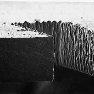
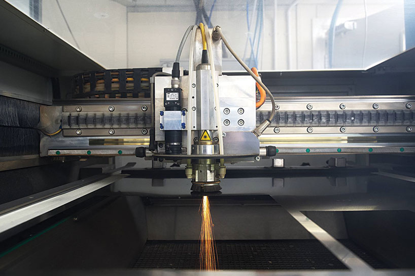
Laser-cut stencils involve directing a focused laser beam to vaporize material from a metal foil, forming precise apertures that match the PCB's land pattern. This method contrasts with older chemical etching techniques, which often result in tapered walls due to isotropic material removal. Stainless steel remains the preferred material because of its durability and compatibility with repeated printing cycles in production environments. Engineers specify stencil thickness based on component pitch, ensuring adequate solder volume without compromising release properties. In fine pitch SMT assembly, where component leads are closely spaced, the straight-sided apertures from laser cutting prevent paste smearing between pads. Adhering to guidelines like those in IPC-7525 ensures consistent aperture dimensions across production runs.
The process begins with importing Gerber data into laser cutting software, where apertures are optimized for print performance. Modern systems achieve positional accuracy within tight tolerances, vital for aligning with fiducials during printer setup. Post-cutting, inspections verify wall straightness and edge quality before use. For electric engineers, understanding these steps helps in specifying stencils that support high-volume assembly without frequent replacements.
Advantages of Laser-Cut Stencils for Fine Pitch Components
Laser-cut stencils outperform chemically etched ones particularly in handling fine pitch components with pitches below typical thresholds. Etched stencils suffer from undercutting, leading to hourglass-shaped apertures that trap solder paste and reduce transfer efficiency. In contrast, laser cutting produces vertical walls, promoting clean paste release onto pads during the wipe cycle. This precision translates to fewer printing defects, such as insufficient paste height or bridging, which plague high-density boards. Engineers benefit from faster turnaround times, as laser fabrication skips multi-step chemical processes and photoresist applications.
Durability is another key advantage, with laser-cut stencils maintaining aperture integrity over thousands of prints. Surface treatments further enhance performance, but the base cutting method sets the foundation for reliability. In SMT assembly lines, this means reduced downtime for stencil cleaning or replacement, optimizing throughput for fine pitch applications. Practical experience shows that teams switching to laser-cut stencils report improved first-pass yields on complex assemblies.
The Critical Role of Aperture Quality in Precision Printing
Aperture quality defines the success of solder paste printing in SMT assembly, directly influencing paste volume, shape, and release. High-quality apertures feature smooth, parallel walls free from burrs or recast layers caused by laser heat. These imperfections can cause paste to stick, leading to inconsistent deposits on fine pitch components. Measuring wall profiles with optical or confocal microscopy reveals deviations that correlate with print defects. Engineers prioritize apertures with high aspect ratios, where thickness does not exceed opening width, to ensure complete paste withdrawal.
Maintaining aperture quality requires precise laser parameters, including power, speed, and assist gas to minimize heat-affected zones. Regular stencil maintenance, such as understencil cleaning, preserves these features over time. In production, poor aperture quality manifests as bridging on adjacent pads or tombstoning during reflow. By focusing on these elements, electric engineers can achieve the repeatability needed for reliable fine pitch SMT assembly.
Electro-Polishing: Optimizing Aperture Surfaces for Superior Performance
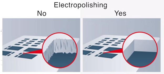
Electro-polishing refines laser-cut stencils by electrolytically smoothing aperture walls, removing microscopic burrs and rounding sharp edges. The process immerses the stencil in an electrolyte bath, where anodic dissolution preferentially erodes peaks on the metal surface. This results in a mirror-like finish that enhances solder paste release, crucial for fine pitch components where even slight adhesion causes defects. Without electro-polishing, laser recast layers can retain paste, leading to low transfer rates and inconsistent deposits.
Benefits extend to extended stencil life, as smoother walls resist paste buildup and wear from squeegee blades. Engineers observe improved print yields, particularly on ultra-fine apertures, due to better area ratios post-polishing. The process also slightly enlarges apertures at the bottom, aiding paste flow without altering nominal dimensions. Integrating electro-polishing into the workflow aligns with best practices for high-precision SMT assembly.
Best Practices for Fabricating and Using Laser-Cut Stencils
Start with accurate data preparation, ensuring Gerber files include fiducials and accurate pad-to-aperture reductions for optimal paste volume. Select stencil thickness inversely proportional to pitch, thinner for finer components to maintain favorable aspect ratios. Laser parameters must balance cut speed with wall quality, avoiding excessive taper or dross. Post-fabrication, electro-polish all stencils intended for fine pitch SMT assembly to maximize aperture quality.
During printing, align the stencil precisely using machine vision, and optimize squeegee pressure and speed for clean snaps. Implement automated understencil cleaning with lint-free materials to prevent residue accumulation. Regular profilometry checks monitor aperture degradation. Following J-STD-001 requirements for solder joints guides overall process validation.
Store stencils flat in protective frames to prevent warping, and audit printing parameters after every shift. These practices ensure consistent performance across production batches.
Troubleshooting Common Challenges in Fine-Pitch SMT with Laser-Cut Stencils
Insufficient solder paste transfer often stems from rough aperture walls or improper squeegee angle, correctable by electro-polishing and angle adjustments. Bridging between fine pitch pads indicates excessive paste volume or poor release, addressed by aperture reductions or slower print speeds. Voids post-reflow may trace to trapped air in apertures, mitigated by ultrasonic cleaning or nanocoating alternatives.
Inspect stencils microscopically for wear after high-volume runs, replacing if wall straightness exceeds tolerances. Printer setup misalignments cause offset deposits, resolved with enhanced fiducial registration. Data errors in Gerber files lead to mismatched apertures, so validate designs pre-fabrication. Systematic troubleshooting rooted in aperture quality maintains high yields.
Conclusion
Laser-cut stencils represent a proven solution for achieving high precision in fine pitch SMT assembly, offering superior aperture quality and reliability. Electro-polishing elevates their performance by ensuring smooth walls and optimal paste release. Electric engineers can leverage best practices in design, fabrication, and troubleshooting to minimize defects and boost production efficiency. By prioritizing these elements, teams achieve consistent results aligned with industry expectations. Investing in quality stencils pays dividends in yield and rework reduction for complex assemblies.
FAQs
Q1: What is a laser cutting stencil and its role in SMT assembly?
A1: A laser cutting stencil is a thin stainless steel sheet with apertures precisely formed by a laser beam for solder paste deposition in SMT assembly. It ensures accurate paste volume on PCB pads, critical for fine pitch components. This method provides straight walls superior to etched stencils, reducing defects like bridging. Proper use enhances alignment and transfer efficiency in high-density production.
Q2: Why are laser-cut stencils preferred for fine pitch components?
A2: Laser-cut stencils excel for fine pitch components due to their precise, vertical aperture walls that promote clean solder paste release. Unlike chemical etching, they minimize taper and burrs, preventing paste retention. This precision supports pitches where small errors cause shorts or opens. Combined with electro polishing, they deliver consistent deposits vital for reliable SMT assembly.
Q3: How does electro polishing improve aperture quality in stencils?
A3: Electro polishing smooths laser-cut stencil aperture walls by removing burrs and recast material through electrolytic action. It creates a polished surface that enhances paste release and reduces bridging in fine pitch SMT. The process slightly enlarges bottom openings for better flow without compromising dimensions. This step is essential for high-yield printing on dense boards.
Q4: What best practices ensure high precision with laser-cut stencils?
A4: Select appropriate thickness for pitch, electro polish for smooth walls, and align precisely with fiducials during printing. Optimize squeegee parameters and clean understencil regularly to maintain aperture quality. Validate Gerber data and inspect stencils periodically for wear. These steps minimize defects in fine pitch SMT assembly, aligning with standards like IPC-7525.
References
IPC-7525 — Stencil Design Guidelines. IPC
J-STD-001 — Requirements for Soldered Electrical and Electronic Assemblies. IPC/JEDEC


