Introduction
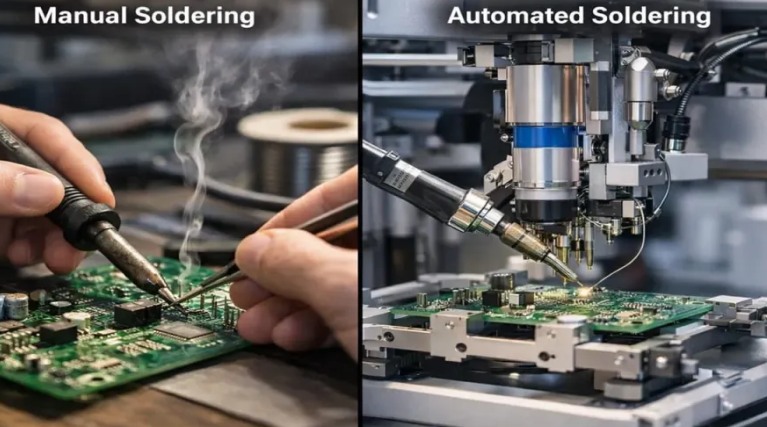
In PCB assembly, choosing between manual soldering stations and automated systems shapes efficiency, quality, and cost outcomes. Electric engineers often face decisions on PCB assembly methods that balance production volume, component complexity, and budget constraints. Manual soldering vs automated soldering becomes critical when developing prototypes or scaling to larger runs. For small batch production, cost effective soldering solutions prioritize flexibility and quick turnaround. This article explores technical differences, practical applications, and troubleshooting insights to guide informed selections. Understanding these options ensures compliance with industry benchmarks while optimizing workflow.
Understanding Manual Soldering Stations
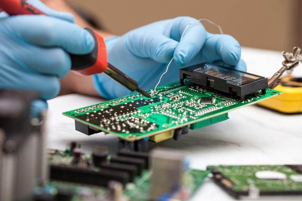
Manual soldering stations typically include temperature-controlled irons, hot air rework tools, and fume extractors for through-hole and surface-mount tasks. Engineers apply solder wire or paste directly, relying on hand-eye coordination to form reliable joints. This method suits soldering for prototype PCBs where design iterations demand rapid changes without retooling. Operators must maintain consistent tip temperature and flux application to avoid defects like cold joints or bridging. Skill levels directly impact joint integrity, making operator training essential for repeatable results. In practice, these stations excel in low-volume environments but require vigilant process control.
Manual stations offer immediate setup for mixed-technology boards, allowing selective heating of components. Troubleshooting issues such as insufficient wetting often traces back to pad contamination or improper tip maintenance. Engineers appreciate the tactile feedback, which aids in detecting anomalies during assembly. However, fatigue can introduce variability over extended sessions, underscoring the need for ergonomic designs. For cost effective soldering solutions, initial investment remains low compared to automated alternatives. Overall, manual approaches align with agile development cycles in engineering labs.
Exploring Automated Soldering Systems
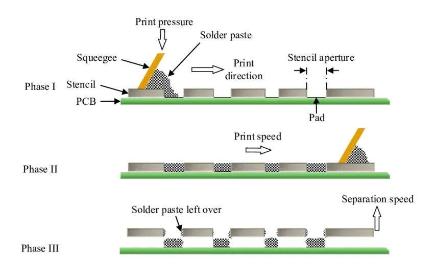
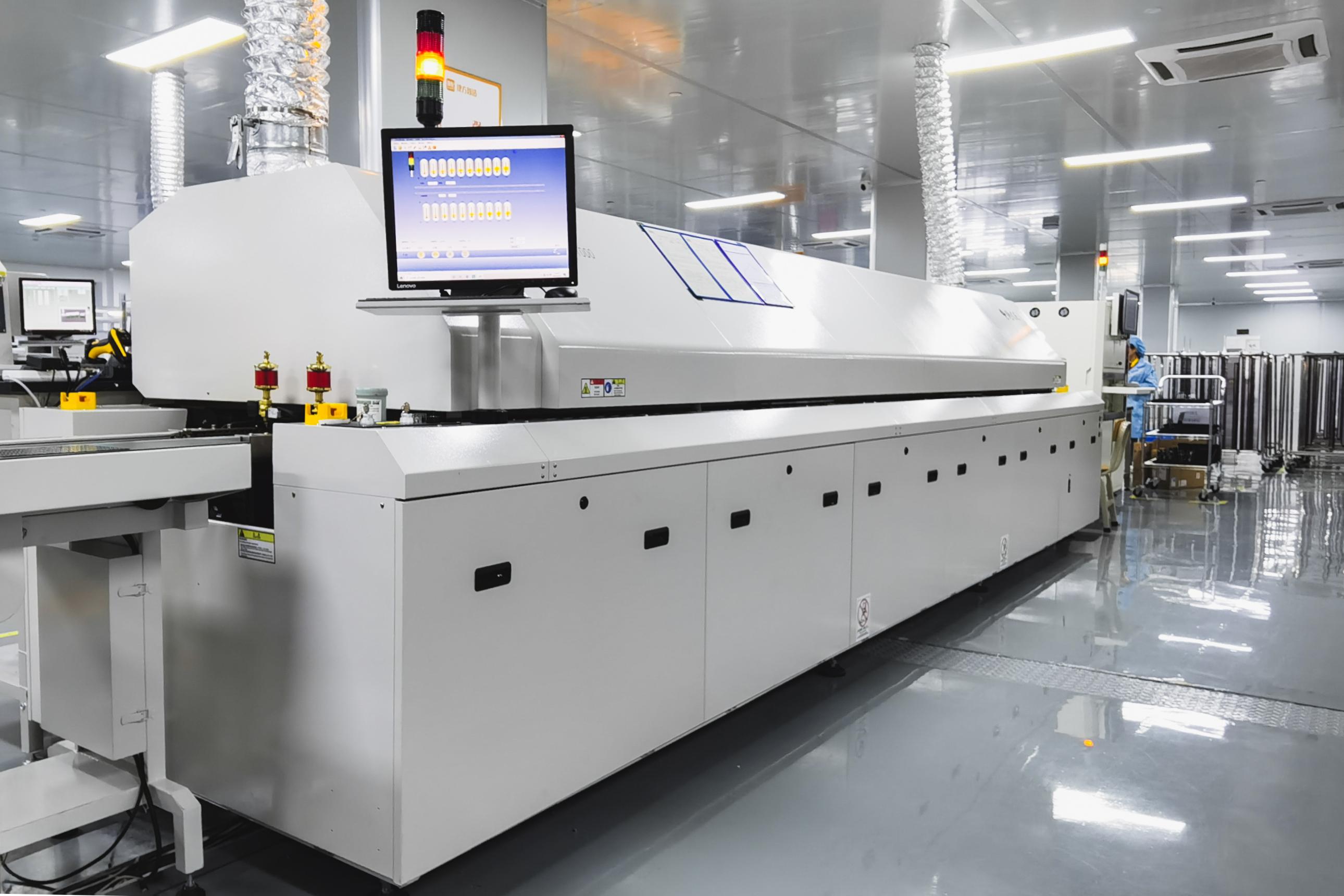
Automated systems encompass reflow ovens for surface-mount technology, wave soldering machines for through-hole components, and selective soldering for hybrid boards. These setups use conveyor belts, precise temperature profiling, and robotic applicators to process multiple boards uniformly. Preheat, soak, reflow, and cool zones ensure solder melts and solidifies predictably across the assembly. Programming flux deposition and component placement integrates with pick-and-place machines for streamlined PCB assembly methods. Such systems demand upfront calibration but deliver high throughput once optimized. Electric engineers value their scalability for medium to high-volume production.
In selective soldering, nozzles target specific vias while masking others, minimizing thermal stress on sensitive parts. Wave soldering immerses pins in molten solder via turbulent or laminar flows, ideal for dense pin counts. Reflow processes vaporize flux and activate solder paste through infrared or convection heating. Monitoring nitrogen atmospheres reduces oxidation in lead-free alloys. These mechanisms adhere to thermal profiles that prevent warping or delamination. Automated precision supports complex boards with fine-pitch components.
Key Differences in Manual Soldering vs Automated Soldering
Manual soldering provides unparalleled flexibility for custom layouts and repairs, whereas automated systems enforce standardized processes for consistency. Operator-dependent manual joints risk human error, while automation achieves uniform heating via controlled ramps. Throughput varies dramatically; manual handles one board at a time, but automated lines process dozens per hour. Initial costs favor manual stations at under equipment budgets for prototypes, yet automation amortizes over large runs through labor savings. Quality metrics, per IPC J-STD-001 requirements for soldered assemblies, apply equally, but automation simplifies compliance through logged profiles.
Thermal management differs significantly between the two. Manual irons deliver localized heat, risking overheating nearby components, while reflow ovens distribute it evenly via zone control. Solder joint voids or excess flux residues appear more in manual work due to application inconsistencies. Automated verification uses inline AOI for real-time defect detection. For PCB assembly methods, manual suits irregular geometries, but automation excels in repeatability. Engineers must weigh these trade-offs against project timelines and defect budgets.
- Flexibility: Manual — High for prototypes and repairs; Automated — Low, requires programming.
- Consistency: Manual — Operator skill-dependent; Automated — High, process-controlled.
- Volume Suitability: Manual — Small batch production; Automated — Medium to high volume.
- Cost Structure: Manual — Low upfront, high labor; Automated — High upfront, low per unit.
- Inspection Needs: Manual — Visual and manual; Automated — Automated optical.
Soldering for Prototype PCBs and Small Batch Production
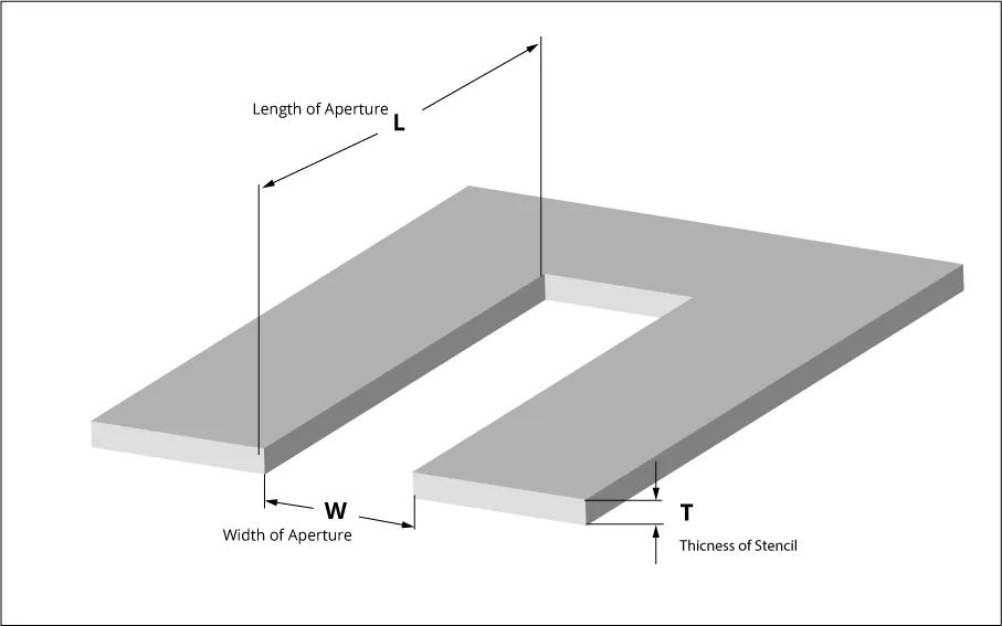
For prototype PCBs, manual soldering stations shine in rapid iteration cycles where design tweaks occur frequently. Engineers can address BGA rework or fine-pitch QFNs without full line reconfiguration. Small batch production benefits from minimal setup, avoiding stencil fabrication delays. Cost effective soldering solutions emerge here, as labor costs stay manageable for runs under 100 units. Troubleshooting unique defects, like tombstoning from uneven heating, proves straightforward with adjustable irons. This approach fosters innovation in R&D phases.
In small batches, manual methods reduce material waste by soldering only populated areas. Compliance with IPC-A-610 acceptability criteria guides visual checks for fillet shapes and wetting. Engineers often pair stations with magnifying aids for precision. Hybrid techniques, combining hand soldering with pre-applied paste, bridge to automation. Such practices maintain quality without scaling infrastructure prematurely. Ultimately, prototypes demand adaptability that manual tools provide reliably.
When Automated Systems Excel in Larger Assemblies
Automated soldering dominates high-volume PCB assembly methods, ensuring joint reliability across thousands of units. Reflow profiles mitigate intermetallic growth in lead-free solders, extending assembly lifespan. Labor efficiency scales exponentially, freeing engineers for design tasks. For dense boards, selective soldering preserves heat-sensitive passives better than broad manual exposure. Integration with ERP systems tracks yield data for process refinement. These systems transform cost effective soldering solutions into volume-driven economics.
Transitioning to automation requires validating thermal models against board stackups. Engineers simulate profiles to match peak temperatures without exceeding component ratings. Post-reflow cooling prevents cracks in ceramics. IPC J-STD-001 outlines material and process controls that automated logging facilitates. Defect rates drop below 1% typically, per industry benchmarks. For production ramps, this reliability justifies the investment.
Best Practices for Reliable Soldering
Regardless of method, preheat assemblies to drive off moisture and activate flux evenly. Maintain tip cleanliness in manual stations with activated sponges or brass wool. Automated fluxers ensure uniform paste volume via laser height sensing. Profile ovens with thermocouples placed at worst-case locations, like thick copper planes. Post-soldering cleaning uses isopropyl alcohol ultrasonics for residue removal. Document processes to trace defects back to variables like ramp rates.
Operator certification under IPC programs builds competency for manual work. Automated systems benefit from periodic nozzle alignments and solder pot skimming. Monitor alloy purity to avoid impurities causing brittleness. For mixed assemblies, sequence through-hole after SMT to leverage reflow tack. These steps enhance yield and support IPC-A-610 class levels. Practical adherence minimizes rework cycles.
Troubleshooting Common Soldering Issues
Cold joints manifest as dull, concave surfaces from rapid cooling, common in manual soldering; extend dwell time or improve flux. Bridging in automated wave soldering stems from excess solder; adjust flux or dwell. Tombstoning in reflow arises from unbalanced wetting; balance paste volumes and profiles. Voids in BGA balls signal outgassing; vacuum reflow or optimized preheat resolves. Manual rework of lifts demands drag soldering techniques. Systematic root cause analysis, per standards, prevents recurrence.
For automated lines, inconsistent conveyor speed causes uneven exposure; calibrate sensors. Manual fatigue leads to bridging; rotate operators and use aids. Thermal profiling tools diagnose profile deviations. Cross-section analysis verifies intermetallics. These troubleshooting tactics ensure robust assemblies.
Conclusion
Selecting manual soldering stations or automated systems hinges on production scale, budget, and flexibility needs. Manual excels in soldering for prototype PCBs and small batch production, offering cost effective soldering solutions with hands-on control. Automated systems provide superior consistency for scaled PCB assembly methods, aligning with high-volume demands. Both adhere to IPC standards for quality. Engineers should prototype manually, then automate for efficiency. This strategic approach optimizes outcomes across project lifecycles.
FAQs
Q1: What are the main advantages of manual soldering vs automated soldering for small batch production?
A1: Manual soldering offers quick setup and flexibility for custom prototypes, ideal for runs under 100 units. It avoids high tooling costs and allows immediate design tweaks. Operators achieve precise control over mixed components. While consistency relies on skill, it provides cost effective soldering solutions. Automation suits larger volumes better.
Q2: When is soldering for prototype PCBs best done manually?
A2: Manual stations shine for prototypes due to rapid iteration and low initial costs. Engineers handle fine-pitch or odd-form parts without programming. Troubleshooting integrates seamlessly during assembly. IPC J-STD-001 guides joint formation. This method supports agile development before scaling. Automated setups add unnecessary delays here.
Q3: How do PCB assembly methods impact cost effective soldering solutions?
A3: Manual methods lower upfront expenses for small batches, emphasizing labor over equipment. Automated reflow reduces per-unit costs in high volume via throughput. Hybrid approaches blend both for transitions. Factor in yield and rework when comparing. Standards like IPC-A-610 ensure quality parity. Choose based on volume forecasts.
Q4: What factors decide between manual and automated soldering in production?
A4: Volume, component density, and budget drive the choice. Manual fits prototypes and repairs with flexibility. Automation ensures repeatability for mass runs. Assess thermal demands and compliance needs. Prototype manually to validate, then automate. This balances cost and quality effectively.
References
IPC J-STD-001 — Requirements for Soldered Electrical and Electronic Assemblies. IPC.
IPC-A-610 — Acceptability of Electronic Assemblies. IPC.