Introduction
Soldering electromechanical components onto printed circuit boards (PCBs) is a critical process in electronics manufacturing. It ensures reliable electrical connections and mechanical stability for components like relays, switches, and connectors. Achieving high-quality solder joints requires understanding various soldering techniques such as reflow soldering, wave soldering, and manual soldering. Additionally, knowledge of solder paste selection, soldering iron tips, and common soldering defects is essential for consistent results. This article provides electrical engineers with a comprehensive guide to mastering electromechanical component soldering techniques. It covers fundamental principles, best practices, and troubleshooting tips to enhance PCB assembly processes. By following industry standards and proven methods, engineers can minimize defects and improve the durability of their assemblies.
What Are Electromechanical Component Soldering Techniques and Why Do They Matter?
Electromechanical components bridge electrical and mechanical functions on a PCB. Examples include connectors, switches, and motors that often have unique shapes, sizes, and thermal requirements. Soldering these components demands precision to ensure both electrical conductivity and mechanical strength. Poor soldering can lead to failures such as intermittent connections or component detachment under stress.
The importance of proper soldering techniques lies in their impact on product reliability. In high-stakes applications like automotive or aerospace, a single defective joint can cause system failure. Moreover, electromechanical components often endure physical stress, making robust soldering vital. By mastering techniques like reflow soldering for surface-mount components or wave soldering for through-hole parts, engineers can achieve consistent quality. Understanding soldering defects and prevention methods further ensures long-term performance in demanding environments.
Technical Principles of Soldering Electromechanical Components
Soldering involves creating a metallurgical bond between a component lead and a PCB pad using a molten alloy, typically composed of tin and lead or lead-free alternatives. The process relies on heat to melt the solder, allowing it to flow and form a joint upon cooling. For electromechanical components, several factors influence the soldering outcome.
Thermal mass is a key consideration. Larger components absorb more heat, requiring precise control to avoid cold joints or overheating nearby parts. Wetting, the ability of solder to spread and adhere to surfaces, depends on clean pads, appropriate flux, and correct temperature. Flux removes oxides and enhances solder flow, but excessive residue can cause corrosion if not cleaned.
Different soldering methods suit specific component types. Reflow soldering uses a controlled oven to melt solder paste for surface-mount devices (SMDs). Wave soldering passes through-hole components over a molten solder wave, ideal for bulk production. Manual soldering, often with a soldering iron, allows precision for rework or small batches. Each method requires tailored parameters to prevent thermal shock or insufficient bonding, especially for electromechanical parts with mixed materials.
Standards like IPC-A-610G, which defines acceptability criteria for electronic assemblies, provide guidelines for solder joint quality. Adhering to such standards ensures consistent results across various soldering techniques.
Soldering Techniques for PCB Assembly
Reflow Soldering for Surface-Mount Electromechanical Components
Reflow soldering is widely used for SMD electromechanical components. It involves applying solder paste to PCB pads, placing components, and heating the assembly in a reflow oven. The oven follows a temperature profile with preheat, soak, reflow, and cooling zones. Preheat prevents thermal shock, while the soak zone activates flux. During reflow, solder melts and forms joints, as per guidelines in JEDEC J-STD-020E for moisture sensitivity.
For electromechanical components, engineers must adjust profiles based on thermal mass. Larger parts may need extended soak times to ensure even heating. Solder paste selection is critical; lead-free pastes often require higher temperatures, risking damage to sensitive components. Regular inspection for defects like tombstoning, where components lift during reflow, is necessary to maintain quality.
Related Reading: The Reflow Soldering Process: A Practical Guide for Electrical Engineer’s Guide
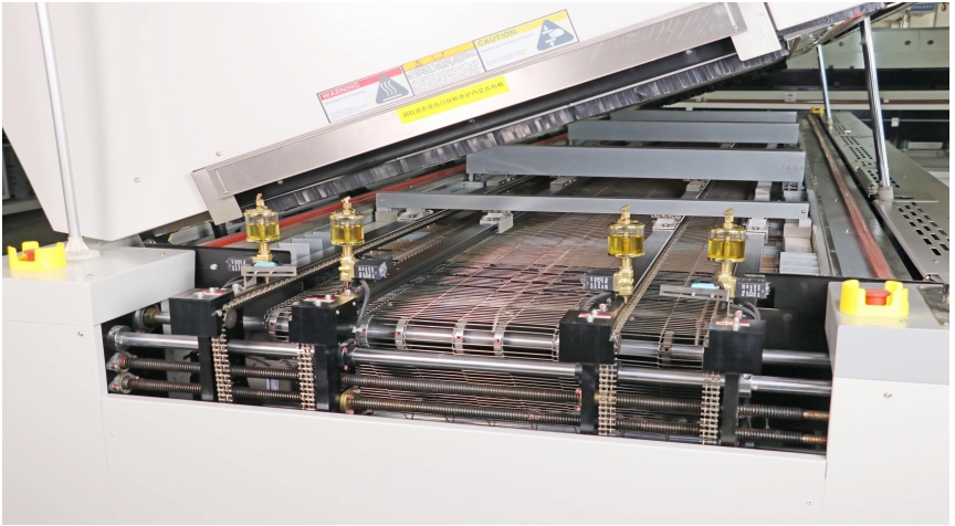
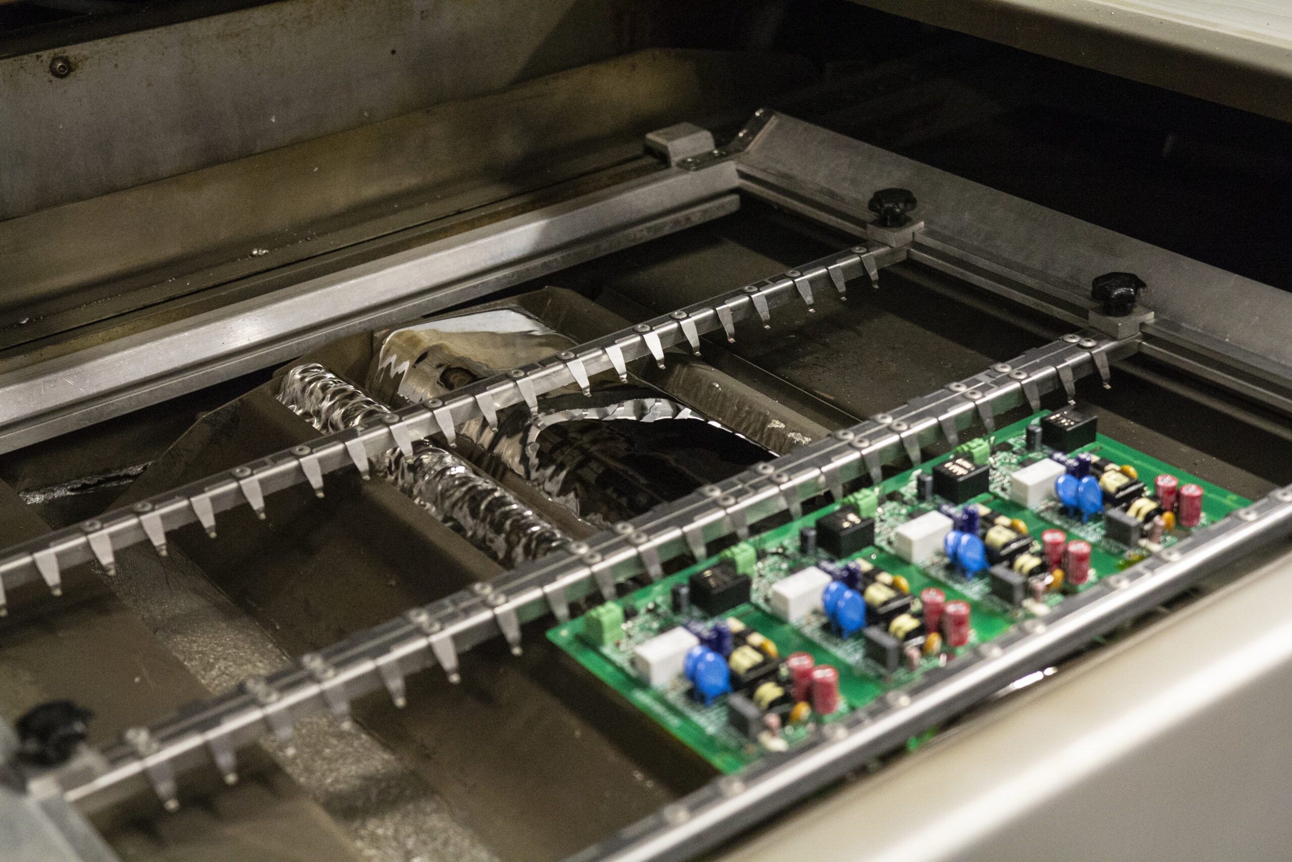
Wave Soldering for Through-Hole Electromechanical Components
Wave soldering suits through-hole electromechanical components like connectors. The PCB passes over a molten solder wave, which wets the exposed leads and pads. Preheating the board minimizes thermal stress, and flux application ensures clean joints. Parameters like conveyor speed and wave height must be optimized to avoid excess solder or bridging between pins.
This method excels in high-volume production but requires careful design. Component orientation and pad spacing influence solder flow, as outlined in IPC-2221B for PCB design standards. Post-soldering cleaning removes flux residues, preventing long-term reliability issues.
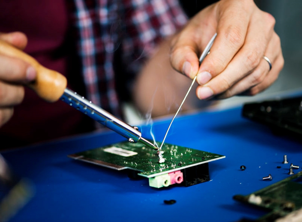
Manual Soldering for Precision and Rework
Manual soldering is indispensable for small batches, prototypes, or rework. It involves a soldering iron to apply heat and solder to joints. For electromechanical components, selecting the right soldering iron tips is crucial. Chisel tips suit larger joints, while fine-point tips work for small pads. Temperature control, typically between 260 to 315 degrees Celsius for lead-based solder, prevents component damage.
Cleanliness is vital in manual soldering. Oxide buildup on tips reduces heat transfer, leading to poor joints. Regular tinning, applying a thin solder layer to the tip, maintains performance. Engineers should follow IPC-A-610G criteria for visual inspection, ensuring joints are smooth and shiny without cracks.
Related Reading: How to Hand Solder Tiny PCB Components (Like 0402 SMDs)
Common Soldering Defects and Prevention Methods
Soldering defects compromise PCB reliability. Understanding their causes helps engineers prevent issues during assembly.
- Cold Joints: These occur when solder does not fully melt, resulting in weak connections. Causes include insufficient heat or dirty surfaces. Prevention involves proper temperature settings and cleaning pads before soldering.
- Solder Bridging: Excess solder creates unintended connections between adjacent pads. It often happens in wave soldering due to close pin spacing. Adjusting solder volume and using solder masks mitigate this issue.
- Tombstoning: In reflow soldering, components may lift on one end due to uneven heating. Balanced pad design and precise solder paste application reduce this risk.
- Insufficient Wetting: Solder fails to adhere properly, often due to inadequate flux or contamination. Using fresh solder paste and maintaining clean surfaces ensures good wetting.
Regular inspection using standards like IPC-A-600K for PCB acceptability helps identify defects early. Automated optical inspection systems can also detect issues in high-volume production.
Best Practices for Solder Paste Selection and Soldering Iron Tips
Solder Paste Selection
Solder paste, a mix of solder alloy and flux, is critical in reflow soldering. Its composition affects melting point, wetting, and joint strength. For electromechanical components, consider the alloy type. Tin-lead pastes offer lower melting points, while lead-free options comply with environmental regulations but demand higher temperatures. Particle size in paste influences printability; finer particles suit small pads.
Flux type within the paste impacts cleaning needs. No-clean fluxes minimize post-soldering residue, while water-soluble fluxes require thorough cleaning to prevent corrosion. Refer to IPC J-STD-004B for flux classification and selection guidance. Testing paste compatibility with components under actual conditions ensures optimal performance.
Soldering Iron Tips for Manual Work
In manual soldering, the soldering iron tip shapes heat delivery. Wide tips transfer more heat for large joints on electromechanical components, while narrow tips offer precision for small pads. Maintaining tips involves regular cleaning with a damp sponge or brass wire to remove oxides. Tinning after cleaning preserves tip life and ensures consistent heat transfer.
Temperature control is equally important. Adjustable irons allow setting specific values based on solder type and component sensitivity. Following manufacturer guidelines and standards like IPC-A-610G ensures safe operation without risking thermal damage.
Troubleshooting Soldering Challenges for Electromechanical Components
Electromechanical components present unique challenges due to their size, material diversity, and mechanical stress. Overheating during reflow soldering can degrade plastic housings in connectors. Using a tailored temperature profile with gradual heating mitigates this risk. In wave soldering, large through-hole components may cause shadowing, where solder fails to reach certain areas. Adjusting wave height and board orientation resolves this issue.
For manual soldering, inconsistent joints often stem from improper technique. Holding the iron too long on a joint risks lifting pads, while insufficient contact leads to cold joints. Practicing steady hand movements and verifying joint appearance against IPC-A-610G standards improves outcomes. Additionally, post-soldering stress testing ensures joints withstand mechanical loads typical in electromechanical applications.
Conclusion
Mastering electromechanical component soldering is essential for reliable PCB assembly. Techniques like reflow soldering, wave soldering, and manual soldering each serve specific purposes, tailored to component types and production needs. Understanding soldering defects, such as cold joints or bridging, enables engineers to implement preventive measures. Proper solder paste selection and maintenance of soldering iron tips further enhance joint quality. By adhering to industry standards and applying best practices, electrical engineers can achieve consistent, durable solder joints. This ensures the performance and longevity of electromechanical assemblies in critical applications.
FAQs
Q1: What are the key factors in selecting solder paste for electromechanical component soldering techniques?
A1: Solder paste selection depends on alloy type, flux composition, and particle size. Tin-lead or lead-free alloys suit different temperature needs, while no-clean or water-soluble fluxes affect post-soldering cleaning. Finer particles improve printability for small pads on electromechanical components. Following standards like IPC J-STD-004B ensures compatibility and reliable joints.
Q2: How can soldering defects be minimized during reflow soldering of PCB assemblies?
A2: Minimizing defects in reflow soldering involves using a proper temperature profile with preheat and soak zones to prevent thermal shock. Balanced pad design and precise solder paste application reduce tombstoning. Regular inspection against IPC-A-610G criteria helps identify issues early, ensuring high-quality joints for electromechanical components.
Q3: What soldering iron tips are best for manual soldering of large electromechanical components?
A3: For large electromechanical components, wide chisel or blade soldering iron tips are ideal due to their ability to transfer sufficient heat to bigger joints. Maintaining tips through regular cleaning and tinning ensures consistent performance. Adjustable temperature control, aligned with IPC-A-610G guidelines, prevents overheating and damage during manual soldering.
Q4: Why is wave soldering preferred for through-hole electromechanical components in PCB assembly?
A4: Wave soldering is preferred for through-hole electromechanical components because it enables bulk soldering in high-volume production. It ensures uniform solder application to exposed leads as the PCB passes over a molten solder wave. Optimizing parameters like preheat and wave height, per IPC-2221B, minimizes defects and ensures strong mechanical bonds.
References
IPC-A-610G - Acceptability of Electronic Assemblies. IPC, 2017.
IPC-A-600K - Acceptability of Printed Boards. IPC, 2020.
JEDEC J-STD-020E - Moisture/Reflow Sensitivity Classification for Nonhermetic Surface Mount Devices. JEDEC, 2014.
IPC J-STD-004B - Requirements for Soldering Fluxes. IPC, 2011.
IPC-2221B - Generic Standard on Printed Board Design. IPC, 2012.


