Introduction
Designing a printed circuit board for mixed assembly involving Surface Mount Technology (SMT), Through Hole Technology (THT), and Ball Grid Array (BGA) components presents unique challenges and opportunities. This approach combines the compactness of SMT, the durability of THT, and the high-density capabilities of BGA to meet diverse performance needs. As modern electronics demand smaller footprints with enhanced functionality, mastering PCB BGA SMT THT design mixed technology becomes essential for engineers. This article explores the principles, best practices, and practical strategies for creating reliable and efficient mixed assembly boards. Aimed at electrical engineers, the content provides actionable insights into design considerations, layout techniques, and assembly processes to ensure optimal performance and manufacturability in mixed technology environments.
What Is Mixed Assembly and Why It Matters
Mixed assembly refers to the integration of multiple mounting technologies on a single PCB, specifically SMT, THT, and BGA. SMT components are soldered directly onto the board surface, offering space efficiency and suitability for automated assembly. THT components, with leads passing through drilled holes, provide mechanical strength for connectors or high-power parts. BGA packages, featuring an array of solder balls underneath, enable high pin counts in compact spaces, often used for complex integrated circuits.
The significance of mixed assembly lies in its ability to balance performance, cost, and reliability. Many applications, such as industrial controls, automotive systems, and consumer electronics, require diverse components that cannot be addressed by a single technology. By leveraging assembly best practices mixed technology, designers can optimize boards for thermal management, signal integrity, and structural durability. Understanding how to design a fast turn PCB for SMT THT BGA ensures that engineers can meet stringent project requirements while maintaining manufacturability.
Technical Principles of Mixed Assembly Design
Mixed assembly design requires a deep understanding of the distinct characteristics of SMT, THT, and BGA technologies. Each method imposes specific constraints on layout, soldering processes, and thermal profiles. SMT components demand precise pad placement and controlled solder paste application to prevent defects like tombstoning or bridging. THT parts need adequate hole sizes and annular rings to ensure secure mounting and soldering, often requiring manual or wave soldering techniques. BGA packages introduce complexities due to their hidden solder joints, necessitating careful via placement and reflow profiles to avoid voids or misalignment.
A critical principle in PCB BGA SMT THT design mixed is managing thermal stress. Different components have varying heat tolerances, and improper soldering can lead to cracking or delamination. Standards like IPC J-STD-020E provide guidelines for moisture sensitivity and reflow conditions, ensuring compatibility across component types. Signal integrity is another concern, as high-density BGA layouts can introduce crosstalk or impedance mismatches if not routed properly. Engineers must also consider mechanical stress, especially for THT parts, which may endure physical strain during operation.
Best Practices for Designing a PCB for SMT, THT, BGA
Creating a successful mixed SMT PCB assembly involves adhering to assembly best practices mixed technology. Below are actionable strategies to guide engineers through the design process.
Component Placement Strategy
Start by prioritizing component placement based on thermal and electrical requirements. Place BGA components first, as they often require specific routing and via configurations. Position SMT parts in areas with minimal thermal stress, grouping similar components to streamline assembly. Reserve space for THT components, ensuring clearance for manual or wave soldering processes. Maintain adequate spacing between components to prevent interference during assembly and to facilitate inspection.
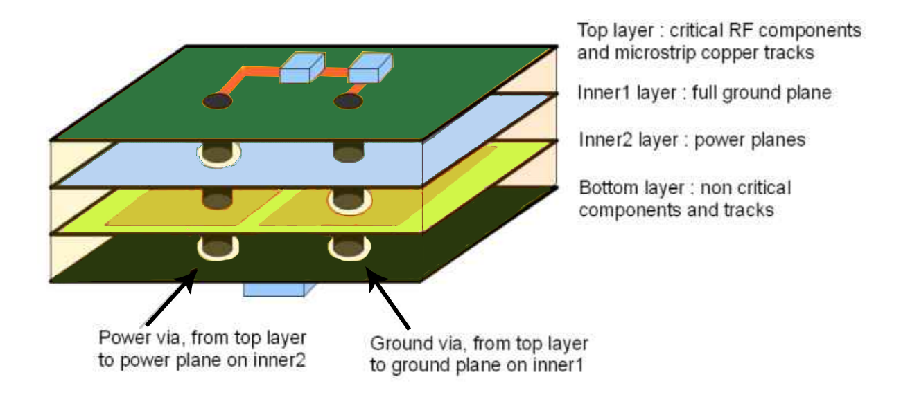
Layer Stackup and Routing
Design the layer stackup to support signal integrity and power distribution. For BGA components, use microvias or buried vias to manage high-density connections without compromising board space. Dedicate inner layers for ground planes to reduce noise, especially near BGA and SMT areas. Route THT leads with sufficient annular rings as per IPC-6012E standards to ensure mechanical stability. Keep high-speed signals away from THT holes to minimize interference.
Thermal Management
Address thermal dissipation by incorporating heat sinks or thermal vias near high-power components. BGA packages often generate significant heat, requiring careful placement of thermal reliefs to avoid solder joint failures. Follow guidelines from IPC J-STD-020E for reflow profiles to prevent thermal shock across SMT, THT, and BGA parts. Ensure that the board material matches the thermal expansion coefficients of components to reduce stress.
Pad and Via Design
Customize pad sizes and shapes based on component type. SMT pads should align with footprint recommendations to ensure proper solder paste application. THT holes must meet minimum diameter and annular ring specifications as outlined in IPC-A-600K for reliable soldering. For BGA, implement a dog-bone via pattern to facilitate breakout routing while maintaining signal integrity. Avoid placing vias directly under BGA balls unless necessary, as this can lead to soldering issues.

Assembly Process Compatibility
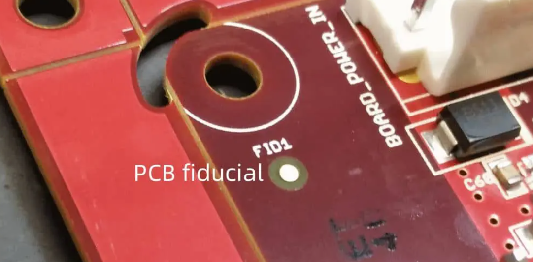
Design with assembly in mind by considering the sequence of soldering processes. SMT and BGA components typically undergo reflow soldering first, followed by wave or manual soldering for THT parts. Ensure that the board layout accommodates this sequence without exposing sensitive components to excessive heat. Use fiducial markers for precise alignment during automated assembly of SMT and BGA elements.
Troubleshooting Common Issues in Mixed Assembly
Mixed assembly boards often encounter specific challenges during design and production. One frequent issue is solder joint failure in BGA components due to improper reflow profiles. Adhering to IPC J-STD-020E can mitigate this by ensuring correct temperature ramps and dwell times. Another concern is mechanical stress on THT components, which can be addressed by reinforcing mounting holes as per IPC-6012E guidelines.
Signal interference between high-density BGA routes and nearby SMT traces is also common. Engineers should implement controlled impedance routing and maintain separation as recommended by design standards. Warpage during assembly can affect all component types, so selecting board materials with appropriate thermal properties and following IPC-A-600K acceptability criteria is crucial.
Conclusion
Designing a PCB for SMT THT BGA mixed assembly requires careful planning and adherence to industry standards. By understanding the unique demands of each technology, engineers can create layouts that balance performance, reliability, and manufacturability. Applying assembly best practices mixed technology ensures optimal component placement, thermal management, and signal integrity. Whether addressing high-density BGA routing or ensuring THT mechanical strength, a structured approach to PCB BGA SMT THT design mixed is vital. This guide provides the foundation for creating robust mixed assembly boards that meet the complex needs of modern electronics.
FAQs
Q1: What are the key challenges when designing a PCB for SMT THT BGA mixed assembly?
A1: Designing a PCB for SMT THT BGA involves managing thermal stress, signal integrity, and assembly compatibility. Each technology has unique requirements, such as precise BGA via placement or THT hole sizing per IPC-6012E. Balancing reflow and wave soldering processes is critical to avoid damaging components. Proper layout planning prevents issues like crosstalk or mechanical failure during production.
Q2: How can assembly best practices mixed technology improve PCB reliability?
A2: Assembly best practices mixed technology enhance PCB reliability by optimizing component placement and soldering processes. Prioritizing BGA and SMT layout reduces thermal stress, while adhering to IPC J-STD-020E ensures proper reflow profiles. Strategic spacing and routing minimize signal interference. These practices collectively reduce defects and improve the board's long-term performance under varied conditions.
Q3: What standards should guide PCB BGA SMT THT design mixed projects?
A3: Key standards for PCB BGA SMT THT design mixed include IPC-6012E for board performance, IPC-A-600K for acceptability criteria, and IPC J-STD-020E for moisture and reflow sensitivity. These guidelines ensure consistent quality in component mounting, soldering, and thermal management. Following them helps engineers achieve reliable and manufacturable designs across mixed assembly technologies.
Q4: Why is thermal management critical in mixed assembly PCB design?
A4: Thermal management is vital in mixed assembly PCB design because SMT, THT, and BGA components have different heat tolerances. Improper heat distribution can cause solder joint failures or component damage. Following IPC J-STD-020E for reflow profiles and using thermal vias or heat sinks ensures even dissipation, protecting the board during assembly and operation.
References
IPC-6012E - Qualification and Performance Specification for Rigid Printed Boards. IPC, 2020.
IPC-A-600K - Acceptability of Printed Boards. IPC, 2020.
IPC J-STD-020E - Moisture/Reflow Sensitivity Classification for Nonhermetic Surface Mount Devices. IPC, 2014.


