Introduction
In high-volume SMT production, the stencil printing process sets the foundation for assembly success. Engineers face constant pressure to boost throughput while minimizing defects and costs. Stencil optimization directly impacts solder paste deposition accuracy, influencing reflow yields and overall process efficiency. Poor stencil performance leads to bridging, insufficient paste, or tombstoning, halting lines and driving up rework expenses. This article explores practical strategies to refine stencil usage, drawing on engineering principles for reliable high-volume operations. By focusing on design, maintenance, and printing parameters, teams can achieve significant throughput improvements and cost reductions.
Understanding SMT Stencils and Their Role in High-Volume Production
SMT stencils are precision-etched metal foils, typically stainless steel or nickel, with apertures aligned to PCB pads for solder paste transfer. In high-volume SMT environments, these stencils endure thousands of print cycles, making durability and repeatability critical. The stencil determines paste volume, shape, and placement, directly affecting joint formation downstream. Suboptimal designs amplify variability, slowing throughput and increasing scrap rates. Engineers must balance fine-pitch requirements with robust construction to sustain process efficiency. IPC-7525 provides foundational guidelines for stencil fabrication, emphasizing aperture geometry and thickness selection.
Stencil types include laser-cut, electroformed, and etched variants, each suited to specific production scales. Laser-cut stencils offer cost-effective precision for high-volume runs due to quick turnaround and smooth walls. Electroformed options excel in ultra-fine pitches but at higher upfront costs. Selection hinges on component mix, pitch density, and cycle volume. Mismatches here undermine stencil optimization efforts, leading to inconsistent paste release.
Key Technical Principles of Stencil Design for Optimization
Stencil thickness profoundly influences paste volume and release efficiency. Thinner stencils, around 0.1 mm, suit fine-pitch components to prevent bridging, while thicker ones, up to 0.15 mm, support larger pads in mixed-technology boards. IPC-7525 recommends thickness based on aperture aspect ratio, targeting an area ratio exceeding 0.66 for clean release. This ratio, calculated as aperture area divided by wall area, ensures paste snaps off without residue. Engineers troubleshoot low ratios by adjusting aperture shapes, such as trapezoidal or U-forms, which reduce wall contact.
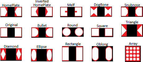
Aperture design drives stencil optimization in high-volume SMT. Standard practice reduces aperture size 5 to 10 percent from pad dimensions to control volume and avoid excess paste. For BGAs and CSPs, home-plate or scooped shapes improve release on small apertures. Step stencils accommodate varying thicknesses on one frame, ideal for boards with diverse component sizes, minimizing changeovers. Wall finish quality, achieved via polishing or electropolishing, cuts friction for better throughput. Variability in these elements cascades into reflow defects, demanding rigorous design validation.
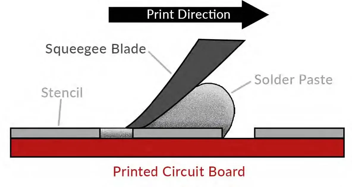
Paste transfer mechanics rely on squeegee dynamics during printing. Snap-off distance, typically 1 to 2 mm, prevents smearing by allowing clean separation. Gasketing between stencil and PCB ensures uniform pressure, critical for warpage-prone panels in high-volume runs. Engineers monitor transfer efficiency, aiming for 75 to 90 percent paste deposition through SPI verification. Deviations signal design flaws or wear, prompting recalibration. Adhering to these principles sustains process efficiency across extended production.
Best Practices for Stencil Usage in High-Volume SMT
Start with material selection tailored to production demands. Stainless steel stencils withstand high-volume SMT abrasion better than nickel, extending life to over 100,000 prints with proper care. Frame rigidity prevents flexing, maintaining alignment during rapid cycles. For stencil optimization, integrate fiducials and tooling holes matching PCB features for sub-micron registration. Automated handling systems further boost throughput by reducing manual interventions.
Printing parameter tuning unlocks throughput improvements. Squeegee speed of 20 to 100 mm/s balances volume consistency with speed, while pressure around 1 to 2 kg/cm2 avoids stencil damage. Multiple print strokes for initial fills ensure even coverage on large boards. Understencil wipe frequency, every 5 to 10 prints, prevents bridging without excessive downtime. Engineers fine-tune via DOE, correlating parameters to defect rates for data-driven stencil optimization.
Cleaning protocols are pivotal for cost reduction. Automated underside cleaners with vacuum and solvent sprays outperform manual methods, minimizing paste buildup and scratches. Frequency scales with paste type; Type 4 or finer requires more aggressive regimens. Post-clean inspection via optical systems detects wear early, averting yield drops. Storage in sealed, humidity-controlled environments preserves surface integrity between runs. These practices cut downtime by 20 to 30 percent in high-volume lines.
Maintenance extends stencil life, directly impacting cost reduction. Regular profilometry checks aperture dimensions, flagging erosion from abrasive pastes. Electropolishing refreshes walls, restoring release properties. For high-volume SMT, modular frames allow quick swaps, sustaining uptime. Tracking print counts per stencil informs replacement cycles, optimizing inventory.
Troubleshooting Common Stencil-Related Issues
Bridging tops defect lists in high-volume SMT, often from excessive paste or poor release. Diagnose by examining aperture walls for residue; clean or redesign with higher area ratios. Insufficient paste volume points to low transfer efficiency, addressed by thicker stencils or optimized snap-off. Tombstoning links to uneven deposition, fixed via symmetric apertures and validated printing parameters.
Misalignment plagues fine-pitch boards, stemming from frame distortion or poor fiducials. Verify vision systems and stencil tensioning. Paste smearing indicates high squeegee pressure or inadequate snap-off; dial back incrementally while monitoring volume. J-STD-001 criteria guide acceptability, ensuring joints meet class standards. Systematic root-cause analysis, using SPC charts, refines stencil optimization iteratively.
Warpage exacerbates issues in panelized high-volume production. Flatness testing pre-printing, per IPC guidelines, prevents gapping. Temporary fixturing holds panels secure. These troubleshooting steps restore process efficiency swiftly.
Conclusion
Optimizing SMT stencil usage transforms high-volume production by enhancing process efficiency and driving throughput improvements. From IPC-7525-informed designs to rigorous maintenance, each facet contributes to defect-free assemblies and cost reductions. Engineers prioritizing area ratios, parameter tuning, and proactive troubleshooting reap sustained gains. Implementing these practices positions teams for scalable, reliable output. Focus on data-backed refinements ensures long-term competitiveness in demanding SMT environments.
FAQs
Q1: How does stencil thickness affect high-volume SMT throughput?
A1: Thinner stencils improve release for fine-pitch parts, reducing bridging and speeding cycles, but demand precise control to maintain volume. Thicker options suit larger components yet risk defects if not optimized. Balance via IPC-7525 area ratios boosts process efficiency. Regular SPI feedback refines selections, minimizing stops for rework in high-volume runs.
Q2: What aperture designs enhance stencil optimization for cost reduction?
A2: U-shaped or home-plate apertures excel for small pitches by improving paste snap-off, cutting residue cleanings. Reduce sizes 5-10% from pads to control volume precisely. Step stencils handle mixed densities, slashing changeover time. These tweaks lower scrap and extend stencil life, directly aiding cost reduction in high-volume SMT.
Q3: How often should stencils be cleaned in high-volume production?
A3: Clean every 5-10 prints based on paste type and defect trends, using automated systems for consistency. Monitor via optical inspection to preempt buildup. Over-cleaning wastes time; under-cleaning spikes bridging. This balances throughput improvement with maintenance, optimizing overall process efficiency.
Q4: What role does IPC-7525 play in stencil troubleshooting?
A4: IPC-7525 offers guidelines on thickness, apertures, and ratios to diagnose issues like poor release or excess paste. Engineers apply it to validate designs against defects. It standardizes practices for repeatable high-volume SMT, supporting data-driven fixes for throughput and yield.
References
IPC-7525C — Stencil Design Guidelines. IPC, 2021
J-STD-001H — Requirements for Soldered Electrical and Electronic Assemblies. IPC, 2018
IPC-7527 — Requirements for Solder Paste Printing. IPC, 2015


